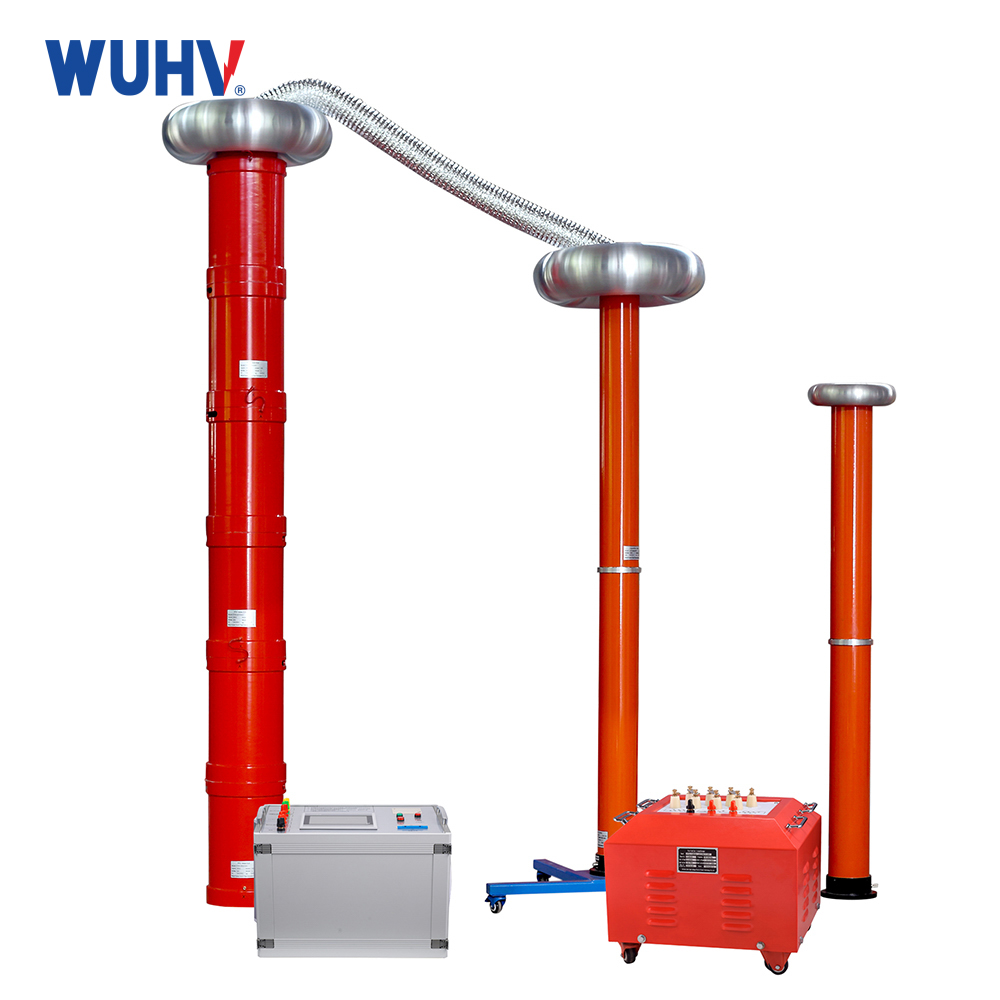
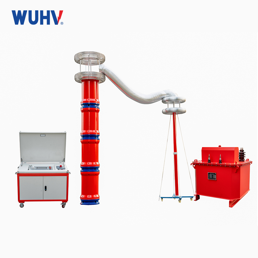
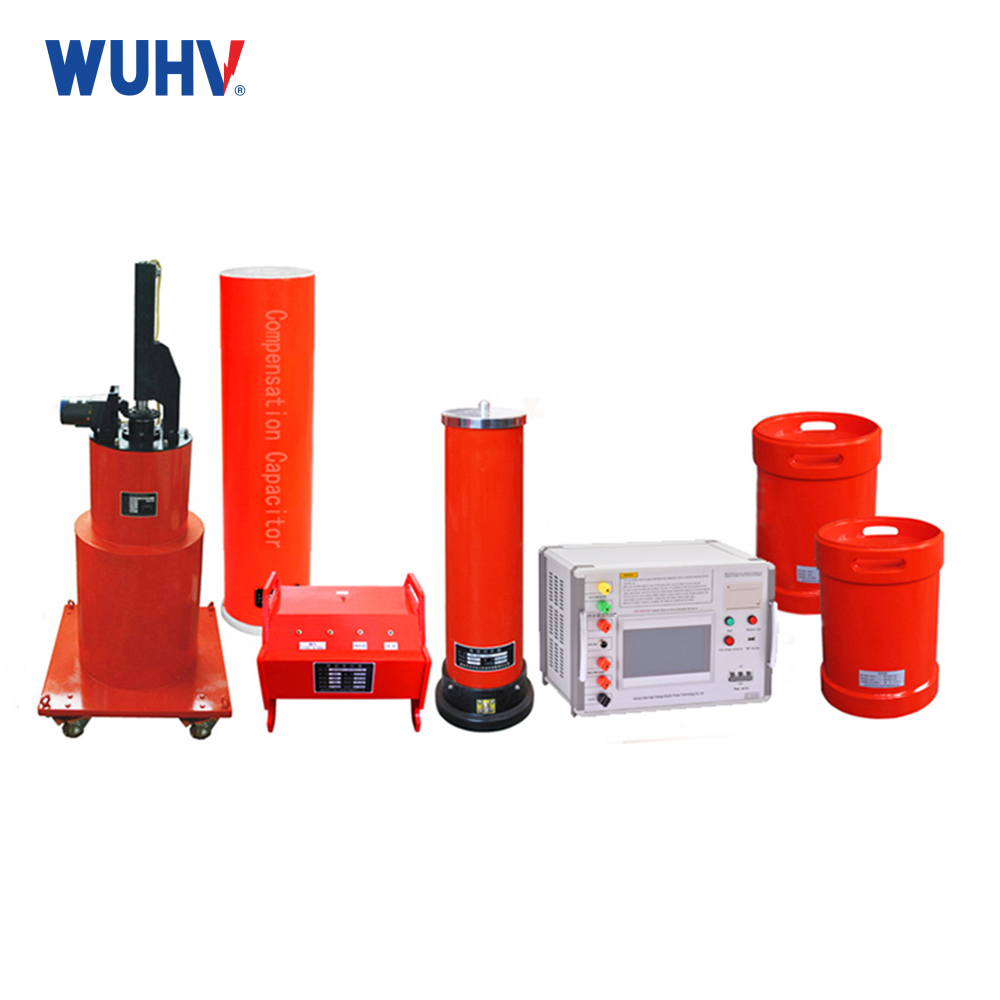
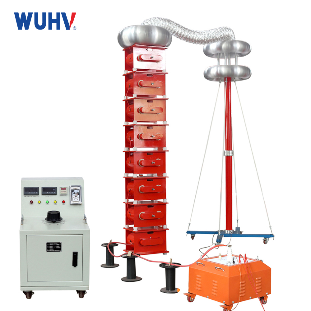
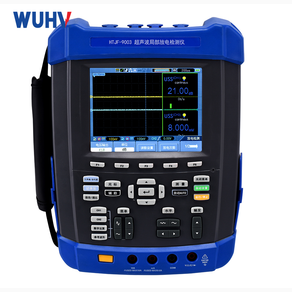
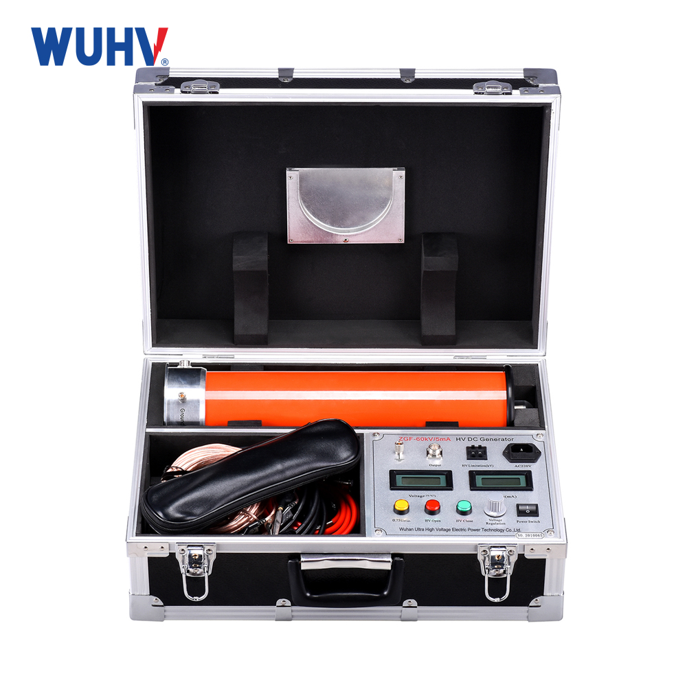
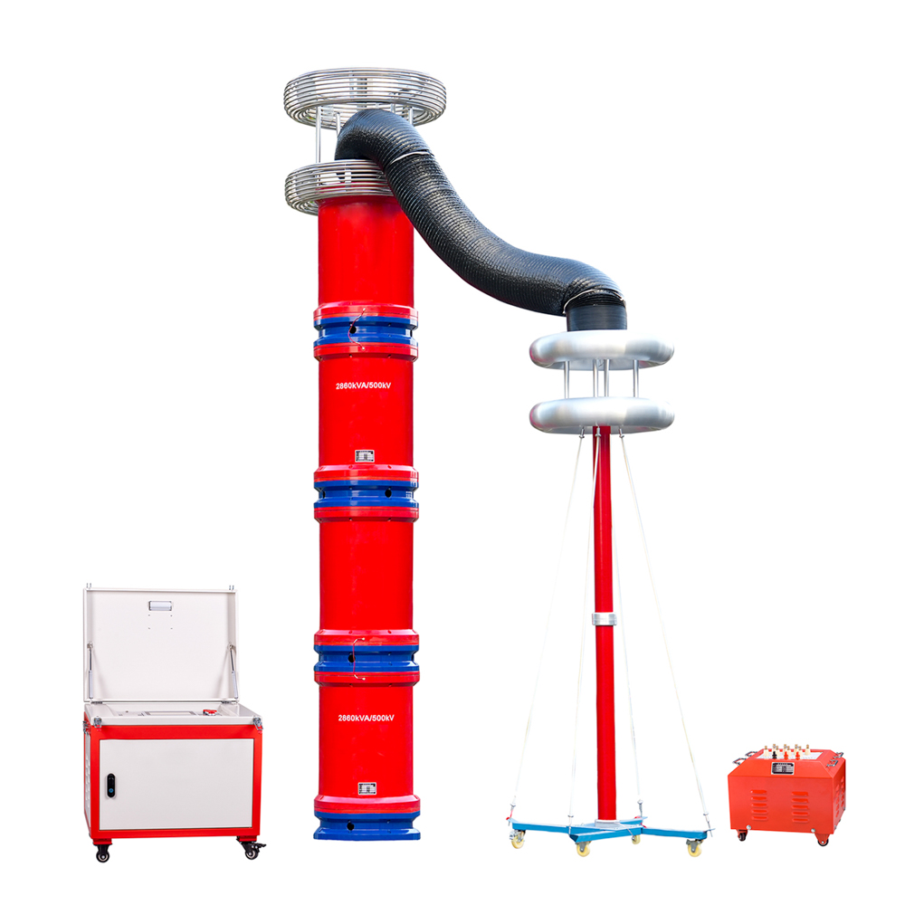
The series resonance under UHV power can help many power workers conduct various power tests more conveniently.
The generation of resonance
In AC circuits with resistors, inductors, and capacitors, the voltage, current, and phase at both ends of the circuit are slightly different. If the parameters of inductance and capacitance or the power frequency are adjusted, the phase can be made the same, the circuit becomes purely resistive, and the circuit reaches this state as resonance.
Resonance is the simple harmonic vibration in physics, where the acceleration of an object is proportional to the displacement away from the equilibrium position and is always directed towards the equilibrium position by the restoring force. The dynamic equation is F=- kx. The phenomenon of resonance is that the current increases and the voltage decreases. The closer it is to the resonance center, the faster the ammeter, voltmeter, and power meter rotate, but the difference from a short circuit is that there will be no zero sequence quantity.
In physics, there is a concept called resonance: when the frequency of the driving force is equal to the natural frequency of the system, the amplitude of the forced vibration of the system is maximized, and this phenomenon is called resonance. The resonance in a circuit actually means that when the excitation frequency of the circuit is equal to its natural frequency, the amplitude of the electromagnetic oscillation of the circuit will also reach its peak. In fact, resonance and resonance express the same phenomenon. This phenomenon with the same essence has different names in different fields.
Resonance application
The radio utilizes the resonance phenomenon. When turning the knob of the radio, it is changing the natural frequency of the circuit inside. Suddenly, at a certain point, the frequency of the circuit became equal to the frequency of the electromagnetic waves that were previously invisible in the air, and they resonated. The distant sound came from the radio. This sound is a product of resonance.
Resonant circuit
A circuit composed of an inductor L and a capacitor C that can resonate at one or several frequencies is collectively referred to as a resonant circuit. In electronic and radio engineering, it is often necessary to select the electrical signals we need from many electrical signals, while suppressing or filtering out the electrical signals we do not need. Therefore, a selection circuit, namely a resonant circuit, is needed. On the other hand, in power engineering, certain hazards such as overvoltage or overcurrent may occur due to resonance in the circuit. Therefore, the study of resonant circuits is of great significance both in terms of utilization and in terms of limiting their harm.
Characteristics during resonance
The characteristics of resonant circuits during resonance include
1. The resonant impedance Z0 is a pure resistor with the minimum value, that is, Z0=R.
2. The current is in phase with the power supply voltage, that is, φ=ψ u - ψ i=0.
3. When the current reaches its maximum value, i.e. I=I0=US/R0, I0 is called the resonant current.
Both ends of L and C may experience high voltage, i.e
UL0=I0XL0=(US/R)XL0=QUS
UC0=I0XC0=(US/R)XC0=QUS
It can be seen that when Q>>1, there is UL0=UCO>>US, so series resonance is also known as voltage resonance. This phenomenon of high voltage is extremely useful in radio and electronic engineering, but it is harmful in power engineering and should be prevented.


