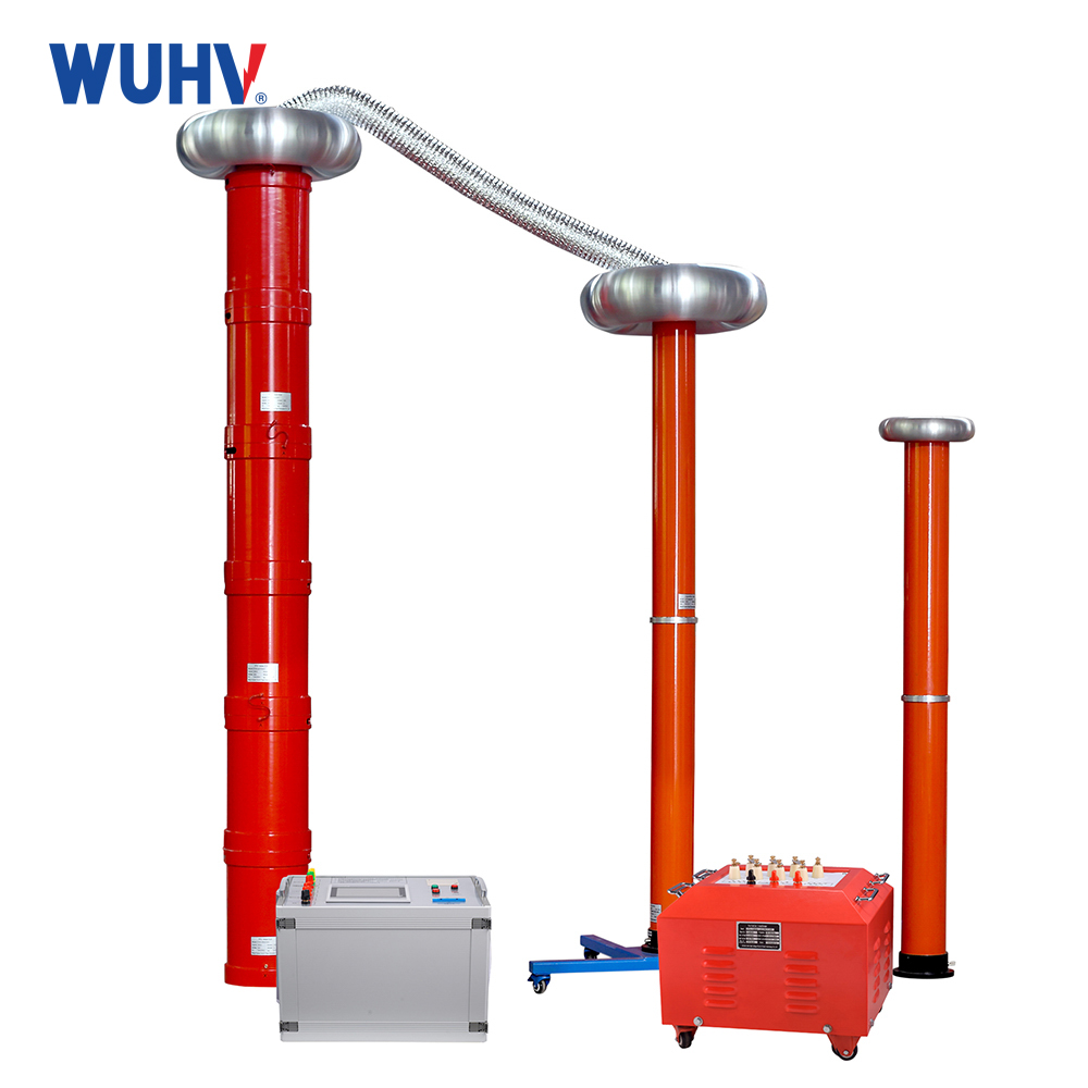
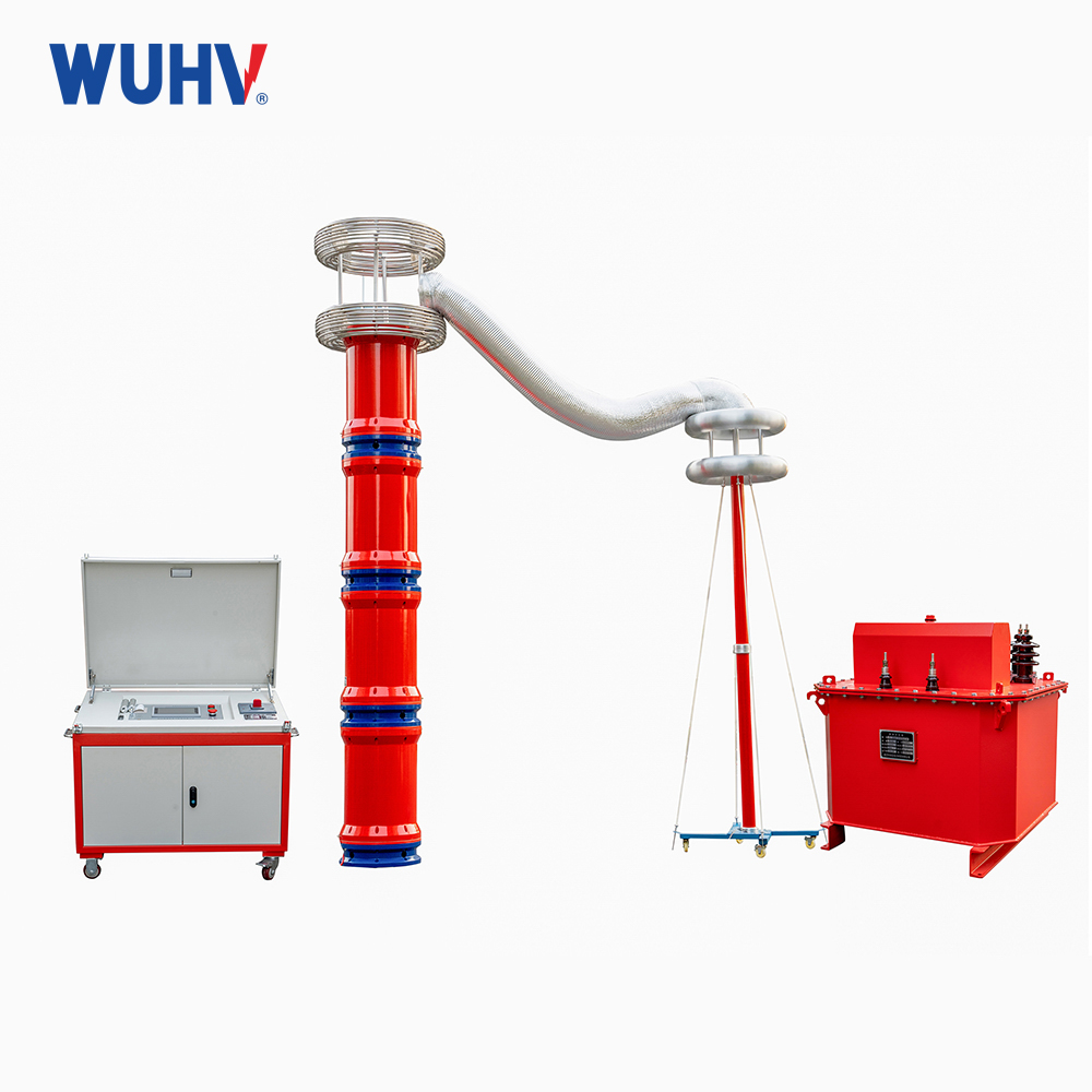
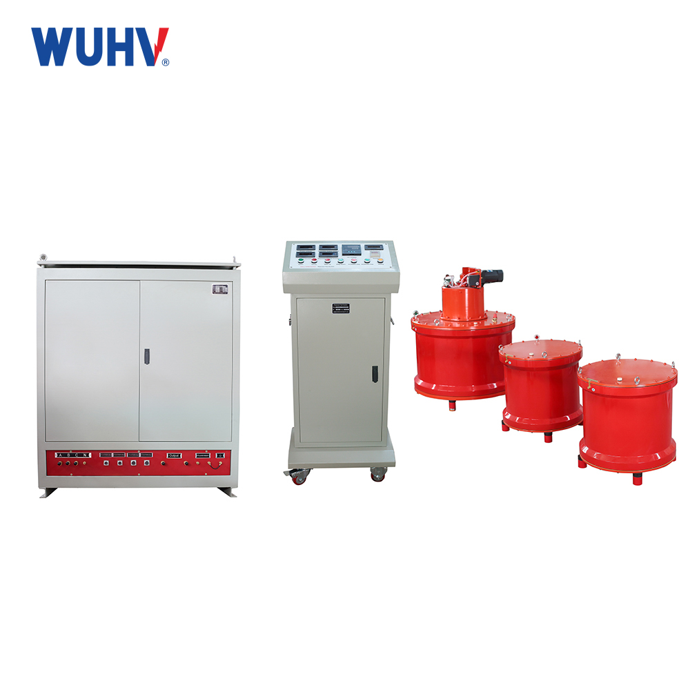
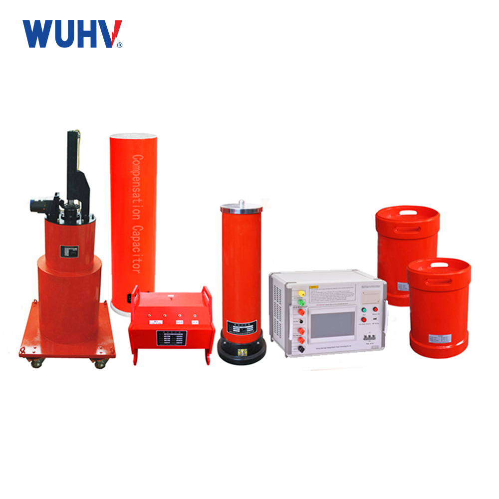
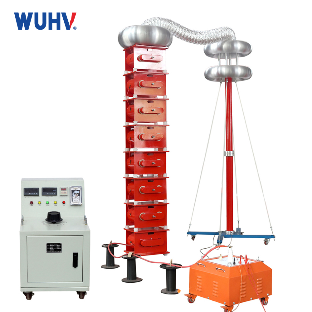
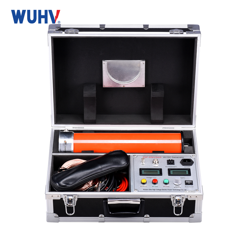
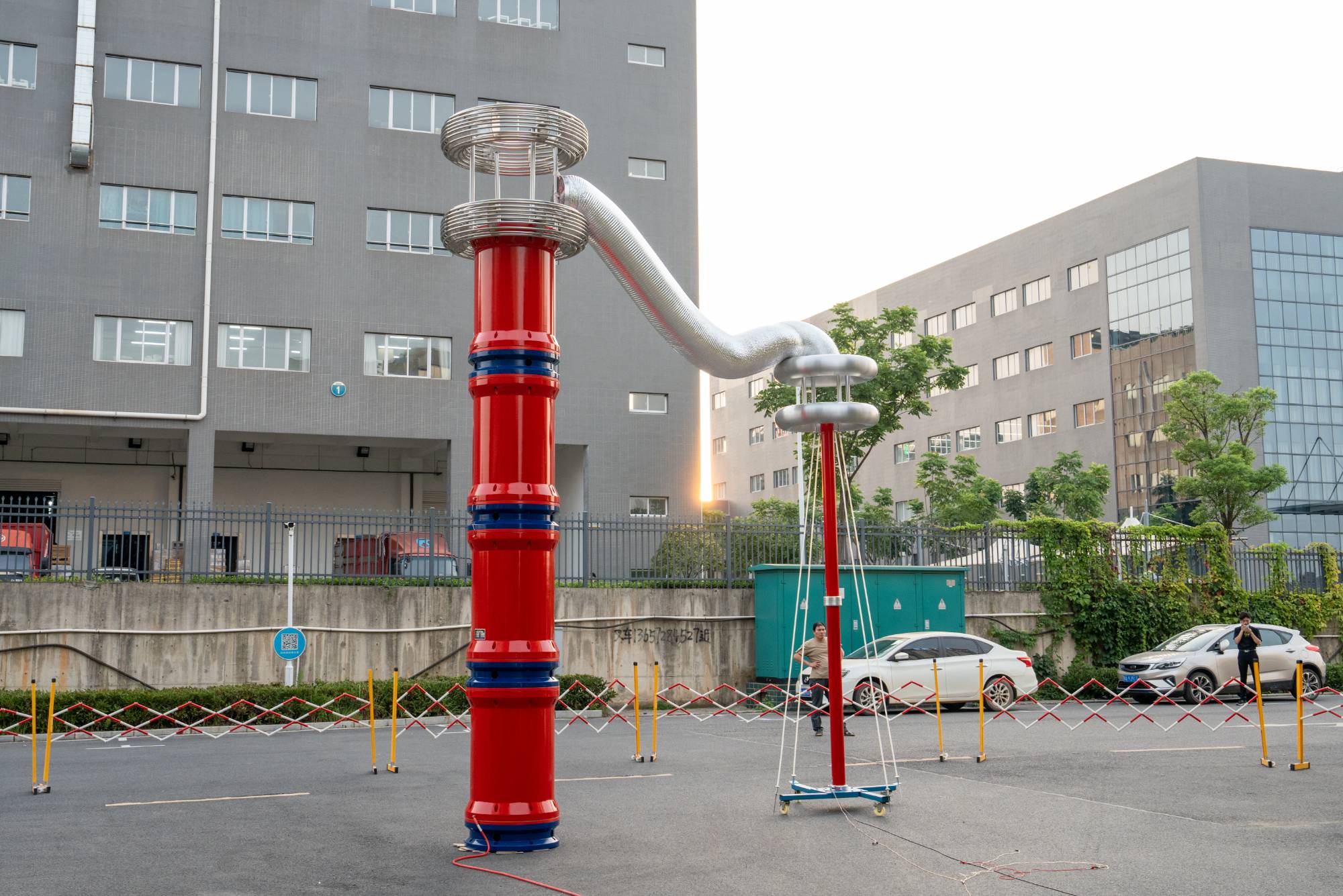
The series resonance under UHV power can help many power workers conduct various power tests more conveniently.
Definition of series resonance
In an AC circuit containing resistor, inductor, and capacitor elements in series, when the power supply voltage U is in phase with the circuit current I, it is called resonance. Since the elements are connected in series, it is called series resonance.
Circuit current: l=U/Z Circuit equivalent impedance: Z=R+J (XL-XC)
According to the definition of series resonance, when a circuit resonates, the circuit current 1 is in phase with the power supply voltage U. According to the basic knowledge of electrical engineering, only when the AC circuit load is purely resistive, the power supply voltage and current are in phase.
As can be seen from the above, circuit resonance has the following obvious characteristics:
(1) The equivalent impedance of the circuit reaches its minimum value and is equal to the resistance component, Z=R.
(2) The equivalent reactance component of the circuit is equal to zero, that is: XL XC=0 XL=XC
(3) According to the formula l=U/z, when the power supply voltage is constant and z equals the minimum value, the maximum value is reached. In the definition of series resonance, it can also be expressed as: in an AC circuit containing resistor, inductor, and capacitor elements in series, when XL=XC (or Z=R), the circuit resonates.
Analysis of current and voltage of each component:
Component current: In a series circuit, the current flowing through each component is the same.
Component voltage:
Resistance voltage UR=U/R * R=U
Inductance voltage UL=U/R * XL=(XL/R) * U
Capacitor voltage UC=U/R * XC -=(XC -/R) * U
Because XL=XC, therefore UL=UC
It can be known that the power supply voltage is equal to the voltage across the resistor, that is, the power supply voltage acts entirely on both ends of the resistor element. The voltage across inductance and capacitance components is numerically equal, with a value equal to X/R (or Xc/R) times the power supply voltage, but with opposite phases.
U: Power excitation voltage
I: Circuit current. Due to the pure resistive nature of the load during resonance, it is in phase with the power supply voltage in the vector.
UR: Voltage across the resistor element. Completely identical to the power supply voltage.
UL: Voltage at both ends of inductive components. Inductive component voltage leads current by 90 °.
UC: Voltage across the two ends of the capacitive element. The voltage hysteresis current of the capacitor component is 90 °.


