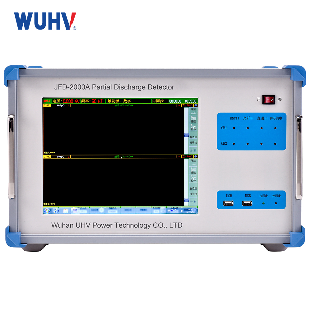
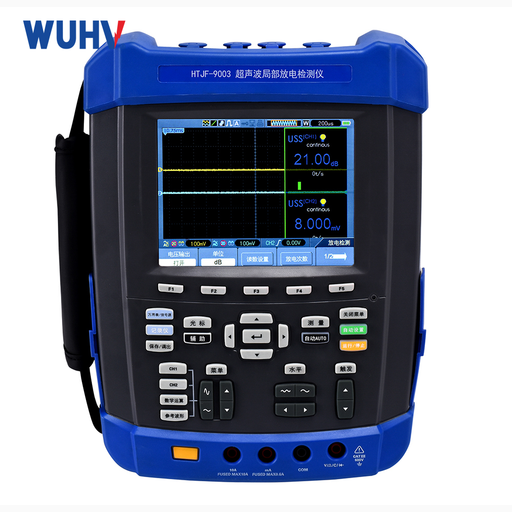
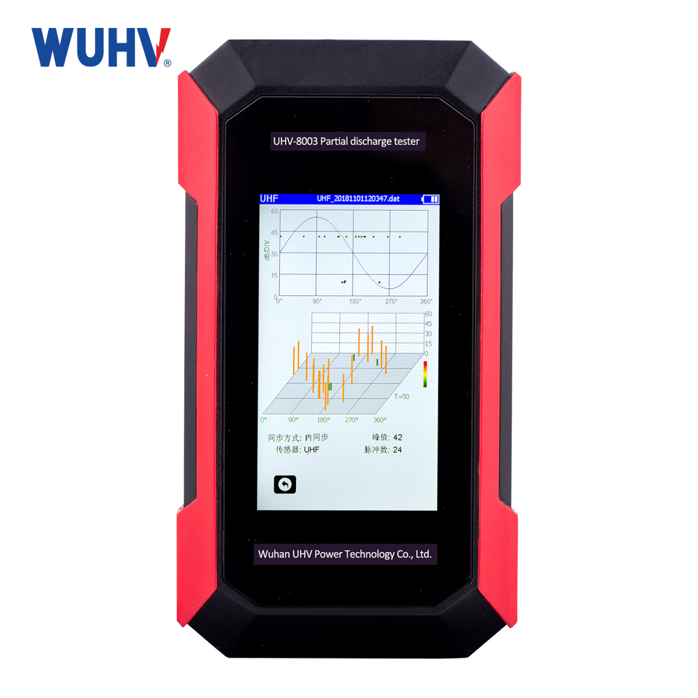
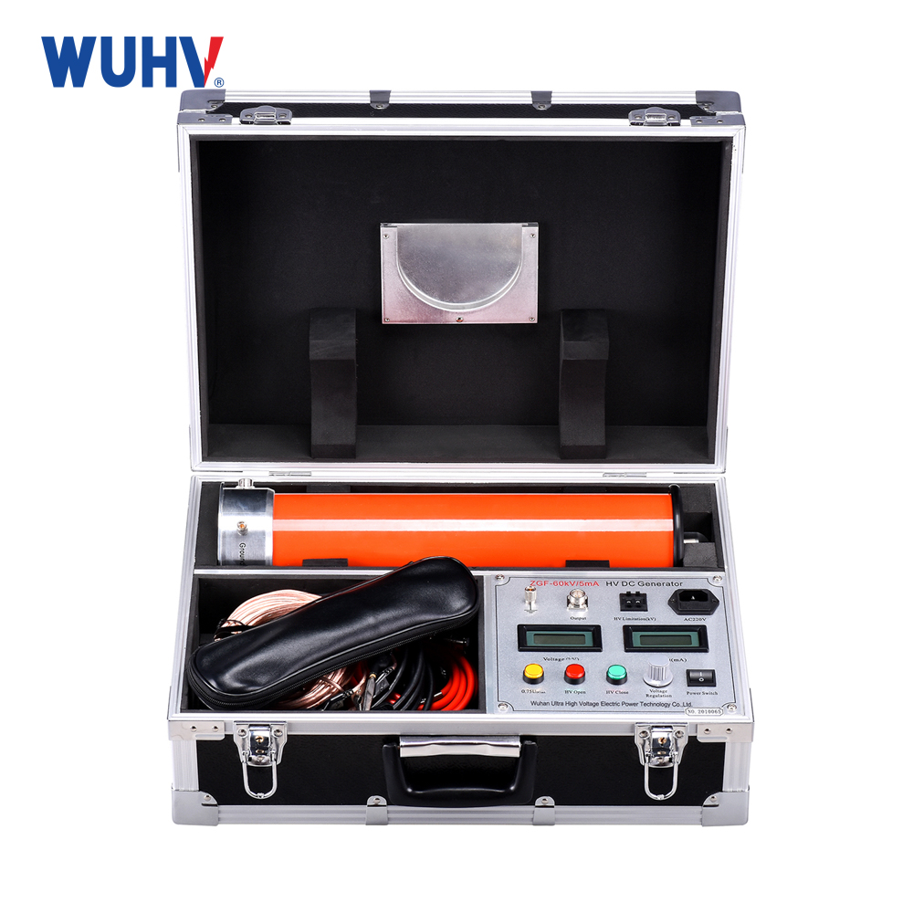
The cable fault location detector under UHV power can help many power workers conduct various power tests more conveniently.
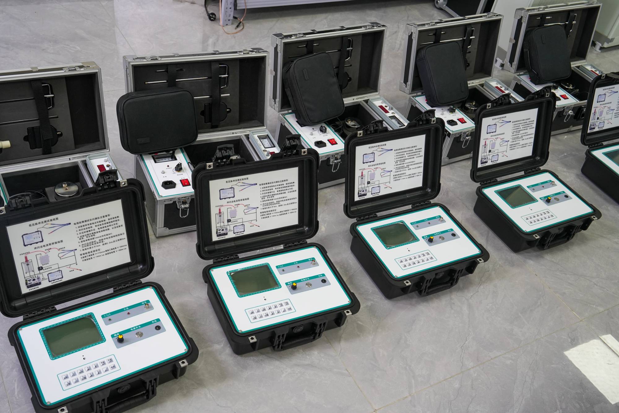
The basic steps of fault testing are to measure the insulation resistance of the faulty cable with a megohmmeter or multimeter, determine the nature of the fault, and determine the testing method; Test the fault distance; Detecting the path of cable burial near the fault point; Fixed point. This testing system has three basic methods for fault testing: low voltage pulse, direct flash, and impulse flash. Combined with different sampling methods, there are a total of eight testing methods. Disconnect all connections at the cable terminals before testing. There are two knobs on the panel of the testing system, "Input Amplitude" and "Displacement", which are used to adjust the signal amplitude and up and down position for the next sampling, respectively.
1. Low voltage pulse method is used to test the speed of radio wave propagation in cables, the total length of cables, low resistance faults, and open circuit faults. Connect the communication cable of the testing system to the serial port behind the laptop. Connect the faulty phase (tested phase) of the cable and the ground wire to the red and black terminals of the water resistance plate, respectively. Connect the output of the water resistance plate to the input of the testing system. The input line of the testing system can also be directly connected to the fault phase and ground wire.
(1) For some cables, the speed of radio wave propagation is unknown and must be determined through testing. But before testing, the total length of the cable must be known. Select "Low Voltage Pulse" and "Measurement Speed" in the "Testing Method" menu, and choose "0.2 μ s" or "2 μ s" according to the length of the cable. Generally, 0.2 μ s is used for cables below 500 meters. After entering the total length of the cable, press the "Sample" button and adjust the "Displacement" and "Amplitude" knobs to ensure that the amplitude and baseline of the signal are in a position that is easy to observe. Move the cursor to the falling edge of the low-voltage pulse and press' locate ', then move the cursor to the front edge of the reflected signal, and the screen will display the propagation speed of the radio waves in this cable. If the transmitted and received waveforms are too close, you can press the "Expand" button to expand the waveform before calculating.
(2) When testing faults, select "Low Voltage Pulse" and "Fault Testing" from the "Testing Method" menu, and choose the appropriate pulse width. After pressing "Sampling", the screen will display the fault waveform.
The reflected signal of an open circuit fault has the same polarity as the transmitted pulse, while the reflected signal of a short circuit fault has the opposite polarity as the transmitted pulse.
2. Flash mode is used to test high impedance leakage faults. Most cable faults can be resolved through flashover testing. In the past, lightning induced voltage sampling was used many times. Usually using the current sampling. Due to the fact that current sampling is not directly connected to high voltage, the safety factor of the human body and equipment is relatively high. If there are multiple faults on a cable or if the cable is extensively damp, the flash resistor sampling method can be used.
3. The direct flash mode and direct flash method are used to test high impedance flashover faults. When using the direct flashing method, please be sure to monitor the high voltage current to prevent the high voltage transformer from burning out due to excessive current.
4. Test the cable path and embedding depth by connecting the output cable of the testing system to one phase of the cable and connecting the ground wire to the cable grounding (lead encapsulation). If the faulty phase has a low resistance value, connect several hundred ohms in series between the output ground and the cable ground. First, adjust the output potentiometer to the minimum value, turn on the power, and adjust the amplitude knob to the appropriate position. At this point, the instrument outputs a 15KHz sine signal, generating an electromagnetic field around the cable. Adjust the "volume" and "fine" knobs of the path signal receiver to make the sound in the headphones clear Very comfortable, you can find the cable path and estimate the depth of cable burial.
(1) When the probe is located at point B above the cable, the coil of the probe is parallel to the electric field, and the coil does not cut off the power line. The induced current in the coil is very small, and there is almost no sound from headphones. When the probe is located at point A or point C, the sound in the headphones is loud. The line formed by the dots with low sound is the path of the cable.
(2) Estimate the burial depth of the cable. The probe is tilted 45 ° to the right at point B above the cable, and then retracted perpendicular to the cable. When retracted to point A, the probe is facing the cable and the sound of the headphones is very low. The distance from point B to point A, that is, the distance to the back, is the depth of cable burial. In this way, the burial depth of the cable can be estimated.
5. We have measured the distance of the fault point using various testing methods, but due to various factors such as measurement errors, remaining cables, and steering, it may not be possible to accurately locate the fault on the ground. It is also necessary to use a fault locator to determine the fault point. At the fault location, high-voltage equipment is used to add a negative DC high voltage to the cable, and the detection point of the cable fault is detected by a locator near the measurement fault point. The preferred time for high-voltage discharge is once every second. Turn on the power of the locator, adjust the volume knob appropriately, and place the locator at the detected cable fault point. There should be sound at the fault point. If the position of the movable locator is not heard, the discharge sound in the headphones is loud, which is the key to failure.
6. Precautions
(1) If the test cable malfunctions, relevant safety rules must be followed.
(2) In high-voltage testing, all equipment should be well grounded to avoid burning out the testing equipment. If available, separate the power supply of the high-voltage generator from that of the testing instrument.
(3) When using high-pressure testing in flammable material environments, safety measures should be taken.
(4) Whenever using a resistor flash, the measured value of waterproofing should be taken.
(5) Pay attention to personal safety.
(6) It is recommended to disconnect the external power supply of the computer when adding high voltage, so there is no need to connect an external mouse.


