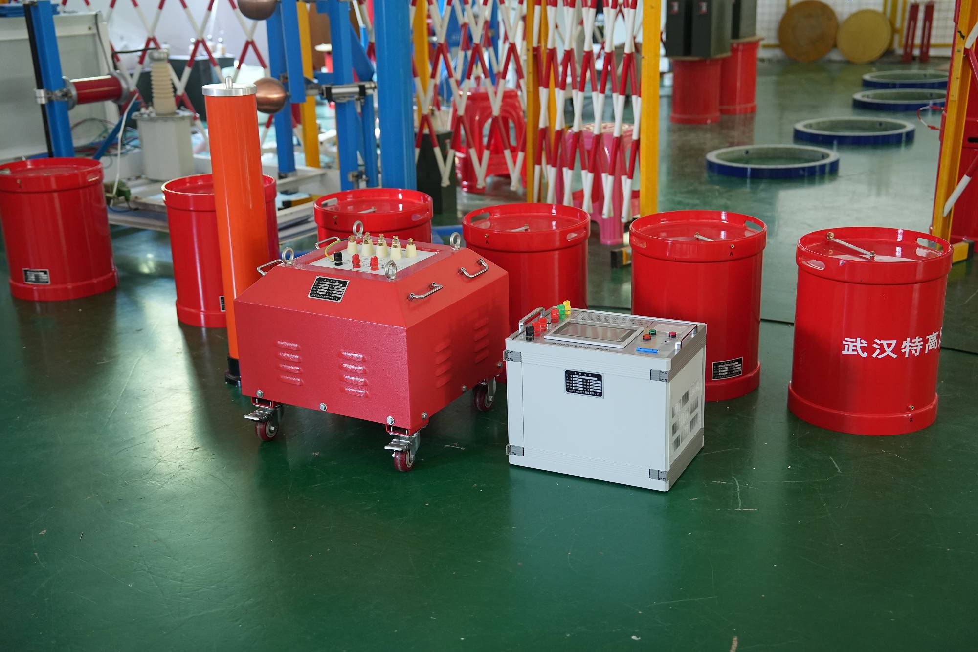
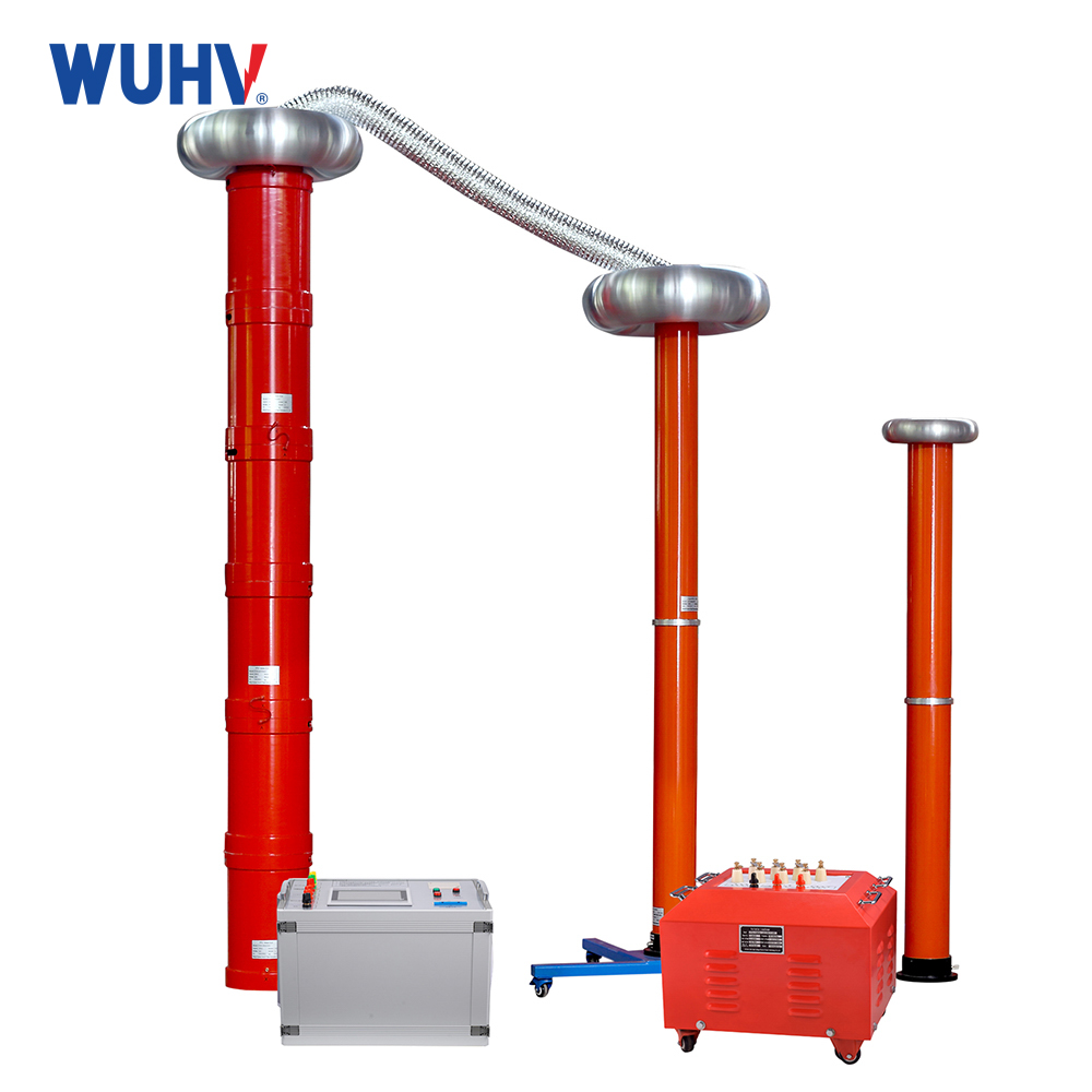
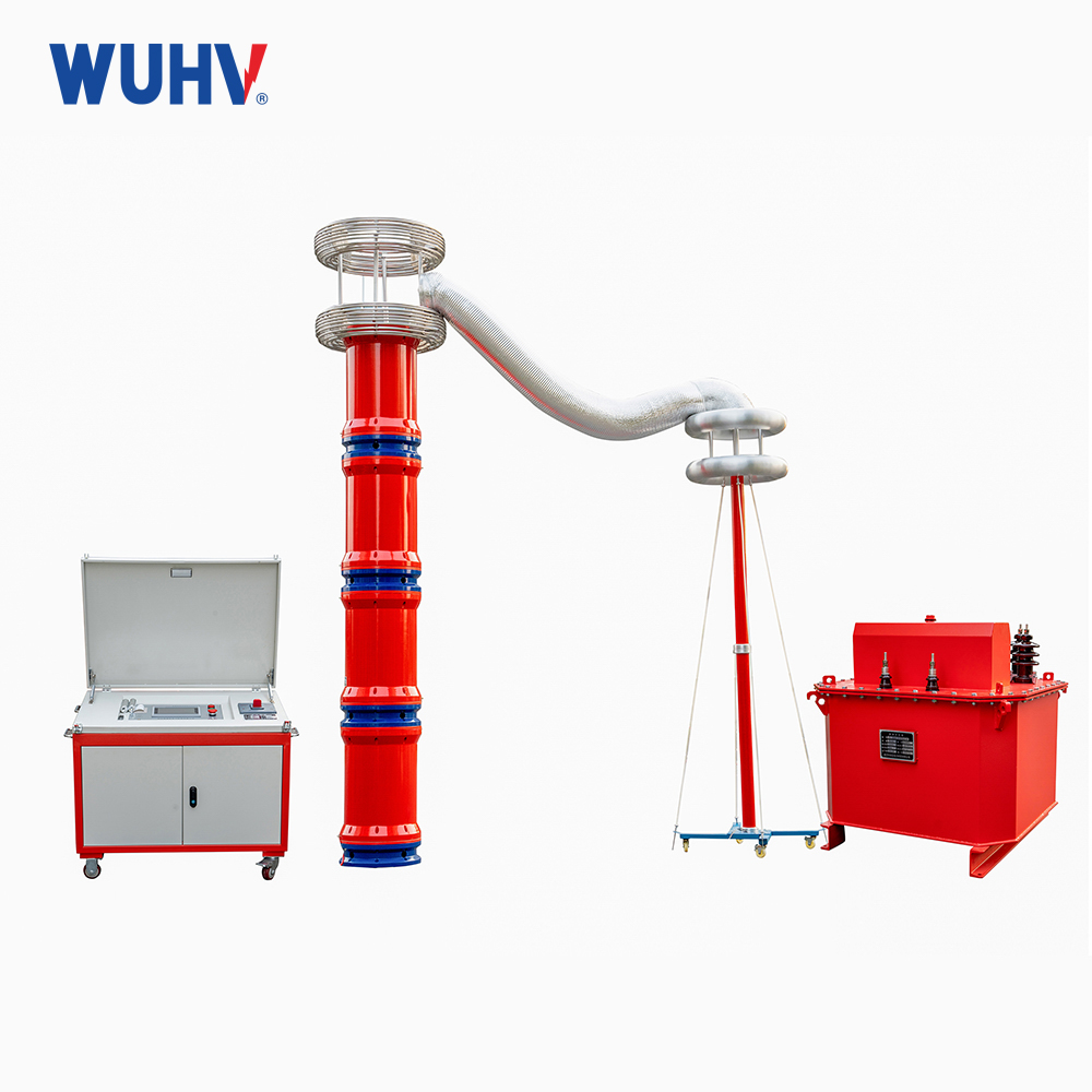
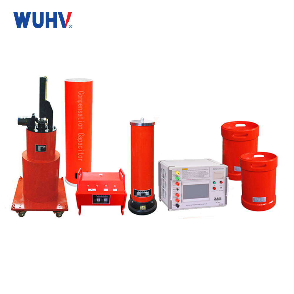
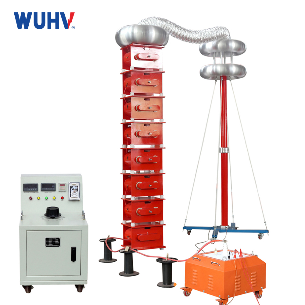
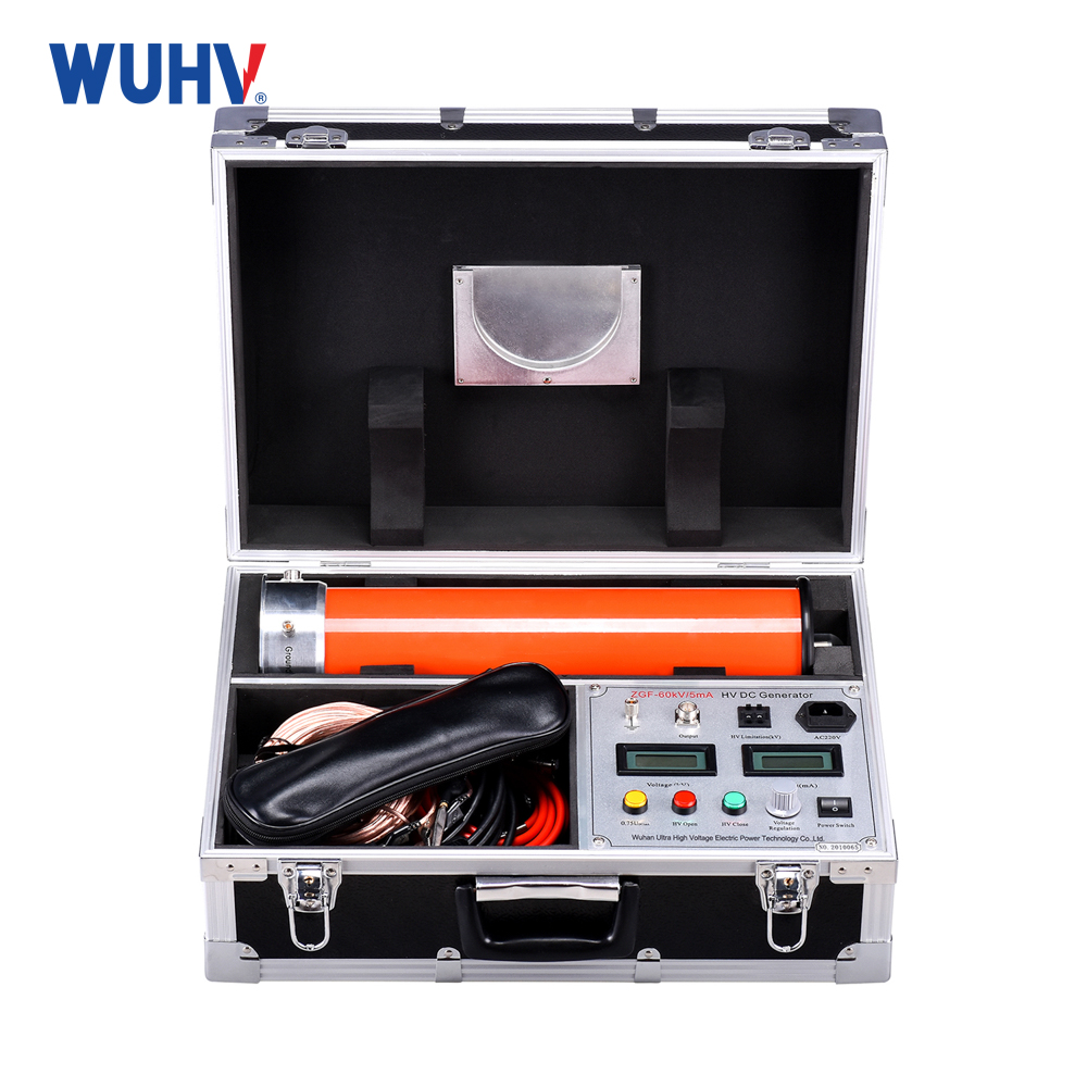
The series resonance under UHV power can help many power workers conduct various power tests more conveniently.
Resonance is one of the most common phenomena in power systems. According to the different forms of harm caused by harmonic resonance, it can be divided into series resonance and parallel resonance. The former is prone to causing overvoltage phenomena. The latter can easily cause overcurrent injuries. Resonance can further exacerbate the distortion of voltage and current, and sometimes even cause damage to power equipment and connecting devices, leading to safety faults in the system.
Series resonant device
The basic characteristic of a series resonant power supply system is the complex combination of inductors and components. When a node or branch of the system experiences nonlinear loads, it is easy to cause resonance in the system. When series resonance occurs, the impedance of the line is minimized, and when nonlinear loads appear at the nodes or branches of the system, the impedance of the line is minimized. This phenomenon occurs in the circuit [13]. The equivalent power supply and impedance diagram at k times frequency are provided Assuming the parameters of the component are fixed at 0 ° V=1 and R~(1) Ω, L~(10),C=μF, The capacitance meets the requirements.
It is easy to find that the impedance of the circuit is the smallest, and the relationship between current and voltage is as follows.
At the resonant frequency, the quality factor Q is close to
Where ω k is the resonant angular frequency. The quality factor represents the voltage amplification of the power supply voltage applied to the inductor.
When the frequency is lower than the requirement, the circuit is equivalent; When the frequency is higher than a higher frequency, the circuit is inductive. It can be considered that the circuit has series resonance at the seventh harmonic, and when the quality factor Q_ (219.91) is reached, the voltage and capacitance of the circuit are severely amplified.
Principles of Branch Method
A branch (component) is the smallest part of a circuit. Whether it is series resonance or parallel resonance, it is a conclusion that overvoltage or overcurrent occurs in the branch (component). In addition, measuring the occurrence of resonance from the perspective of branches can not only check the overcurrent and overvoltage of the device, but also guide the installation and planning of the calibration device. The occurrence of series resonance is closely related to branching, not just nodes or circuits.
For complex linear networks, select the branch to be studied and combine it with the rest of the network. These steps are as follows:
Step 1: Set the voltage or current source in the system to 0;
Step 2: Process the circuit and component parameters of the system based on harmonic impedance (frequency f), including generators, loads, filters, etc;
Step 3: Remove the equivalent impedance of the network after removing the branch.
Step 4: Connect a harmonic voltage source with a frequency of f and an amplitude of 1 unit in series to obtain the current of the branch at this time.
Step 5: Determine if f is greater than the observation frequency range. If so, stop; If not, replace f=f with step 3.
When the testing system is in series resonance state, as long as a small harmonic voltage is connected in series with the corresponding branch, a large harmonic current will be generated in both the branch and the system.


