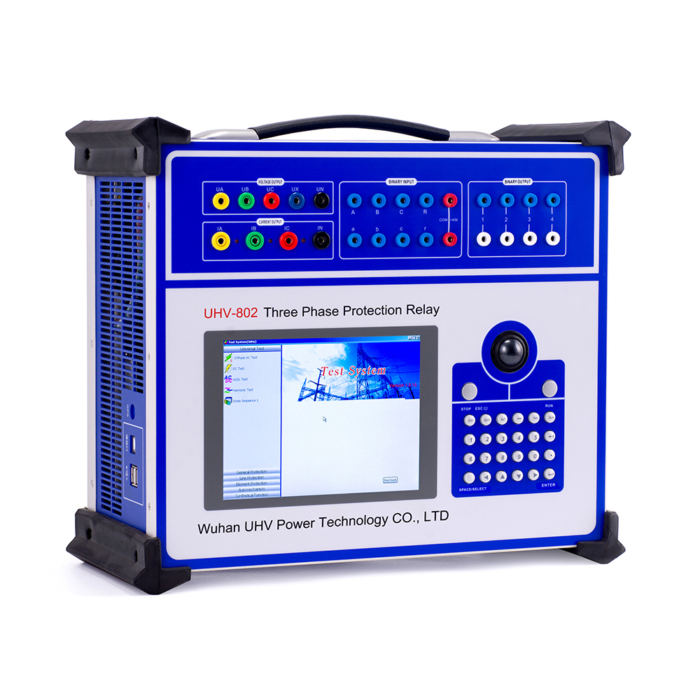
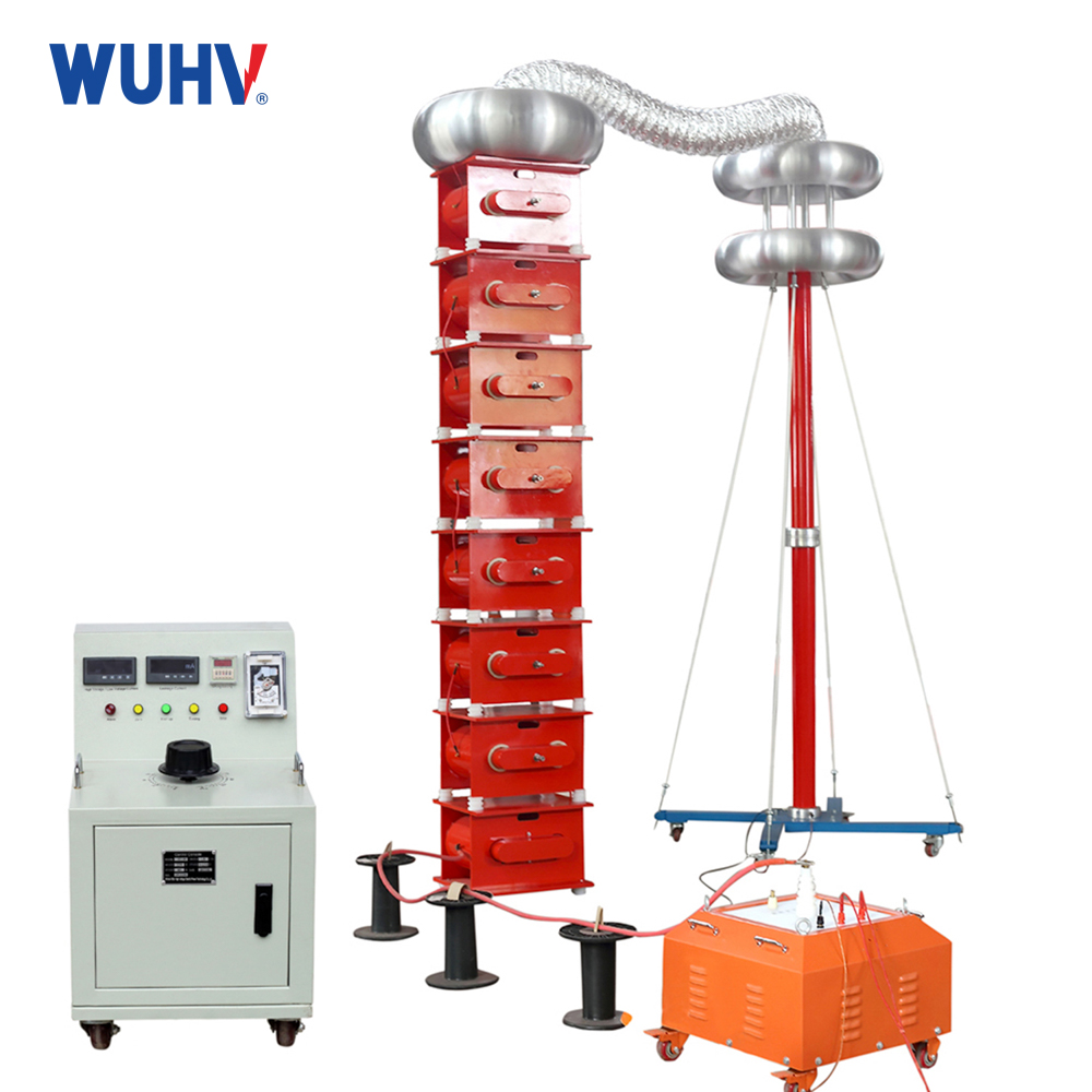
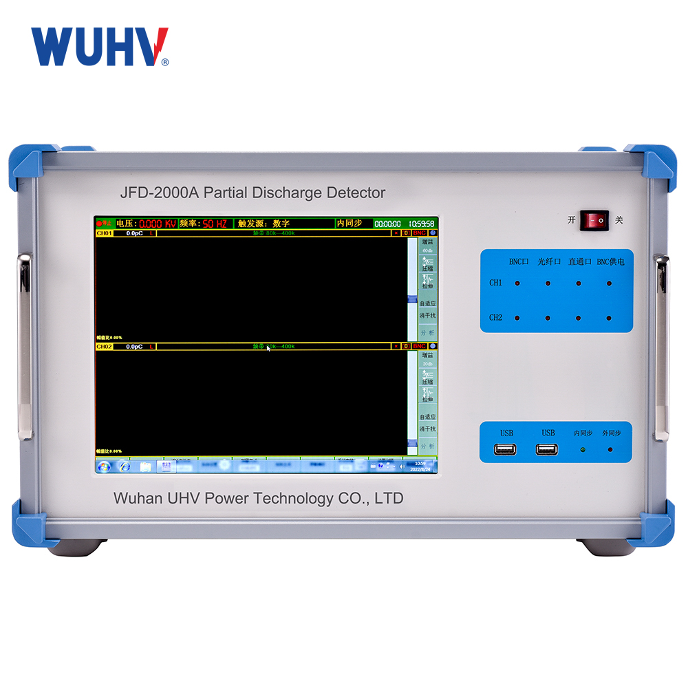
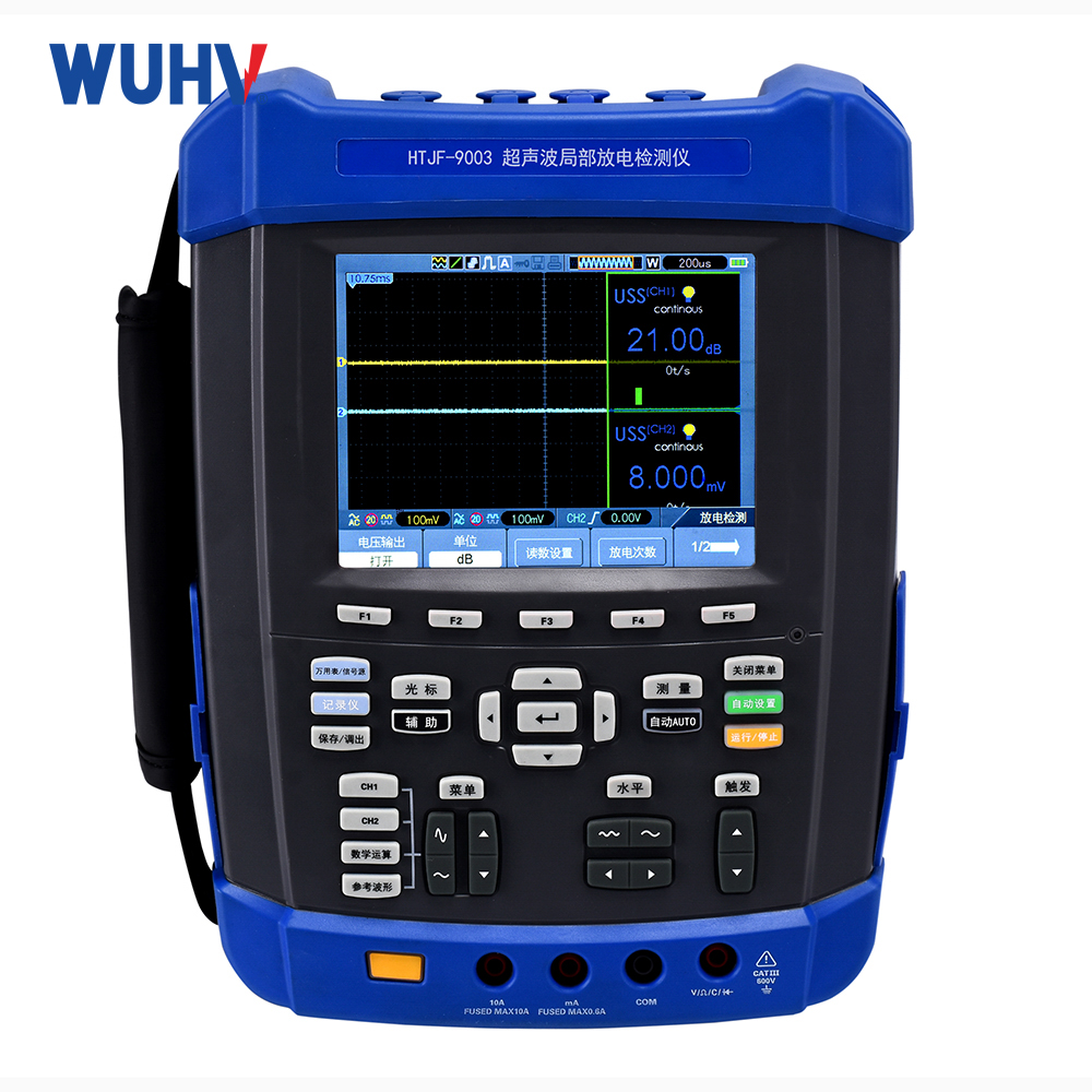
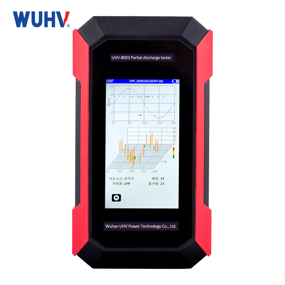
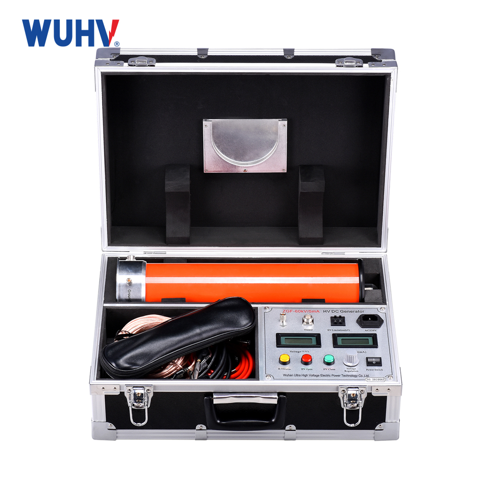
The relay protection tester under UHV power can help many power workers conduct various power tests more conveniently.
The issues that power workers need to pay attention to when using microprocessor relay protection testers for AC testing are summarized as follows:
1. One of the general testing steps for relay protectors is to set the "switch positioning confirmation time". We need to pay attention to setting it larger here, such as around 20ms. If there is a significant error in the test return value, it may be due to the large shaking of the relay contacts. In this case, the test can continue in "manual" mode. To ensure reliable operation of relay protection, it is necessary to ensure that the output of the tester is greater than the starting value of the protection when detecting the relay action time.
2. The conventional method for detecting multi-stage overcurrent protection is to test separately in a section and gradually increase the current until the protection is activated. However, the action time detected through this traditional method is often inaccurate. When detecting the action time at this time, pay attention to directly outputting a positive action value of 1.2 times or more from the tester. At this point, the low voltage protection becomes less than 0.8 times, ensuring the activation of the protection and therefore the measured action time is more accurate.
3. The detection of distance protection requires attention to the conventional setting value of 0.95 times for detection. At this time, the short-circuit impedance is less than the set value to ensure reliable protection and exit. When simulating grounding distance faults, it is also important to pay attention to the correct setting of the zero sequence compensation coefficient.
4. When checking the zero sequence current, it is necessary to distinguish whether the fixed value given in the value table is 3I0 or I0. If customized as I0, display the bottom left corner of the detection module; If customized as 3I0, the value in the bottom left corner will be multiplied by 3 to see if it matches that value.
5. For the detection of low cycle protection, the selection frequency can be changed. The frequency change step size of "automatic mode" is better than that of manual mode. Manual mode is difficult to control because df/dt is locked at a low cycle value. The step size of frequency variation is set according to the accuracy requirements. The frequency has decreased from 50 to provide protection. It should be noted that the interval time is longer than the protection action time.
These are five points to note when conducting AC testing on microprocessor relay protection testers.


