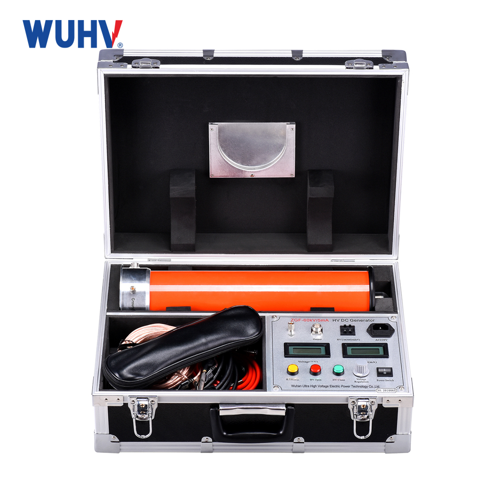
The series resonance under UHV power can help many power workers conduct various power tests more conveniently.
In an AC circuit with resistor R, inductor L, and capacitor C, series resonance generally results in different phases of voltage and current at both ends of the circuit. If we adjust the parameters or power frequency of circuit components (L or C), we can make their phases the same, and the entire circuit appears purely resistive. When a circuit reaches this state, it is called resonance. In the resonant state, the total impedance of the circuit reaches or approximates its maximum value. The purpose of studying resonance is to understand this objective phenomenon and fully utilize its characteristics in science and applied technology, while also preventing the harm it may cause. There are two types of circuit connections: series resonance and parallel resonance. In a series circuit composed of resistors, inductors, and capacitors, when the capacitive reactance XC is equal to the inductive reactance XL, i.e. XC=XL, the phase of the voltage U and current I in the circuit are the same, and the circuit exhibits pure resistance. This phenomenon is called series resonance (also known as voltage resonance). When a series resonance occurs in the circuit, the impedance of the circuit Z=√ R2+XC-XL2=R, the total impedance in the circuit is minimized, and the current will reach its maximum value.
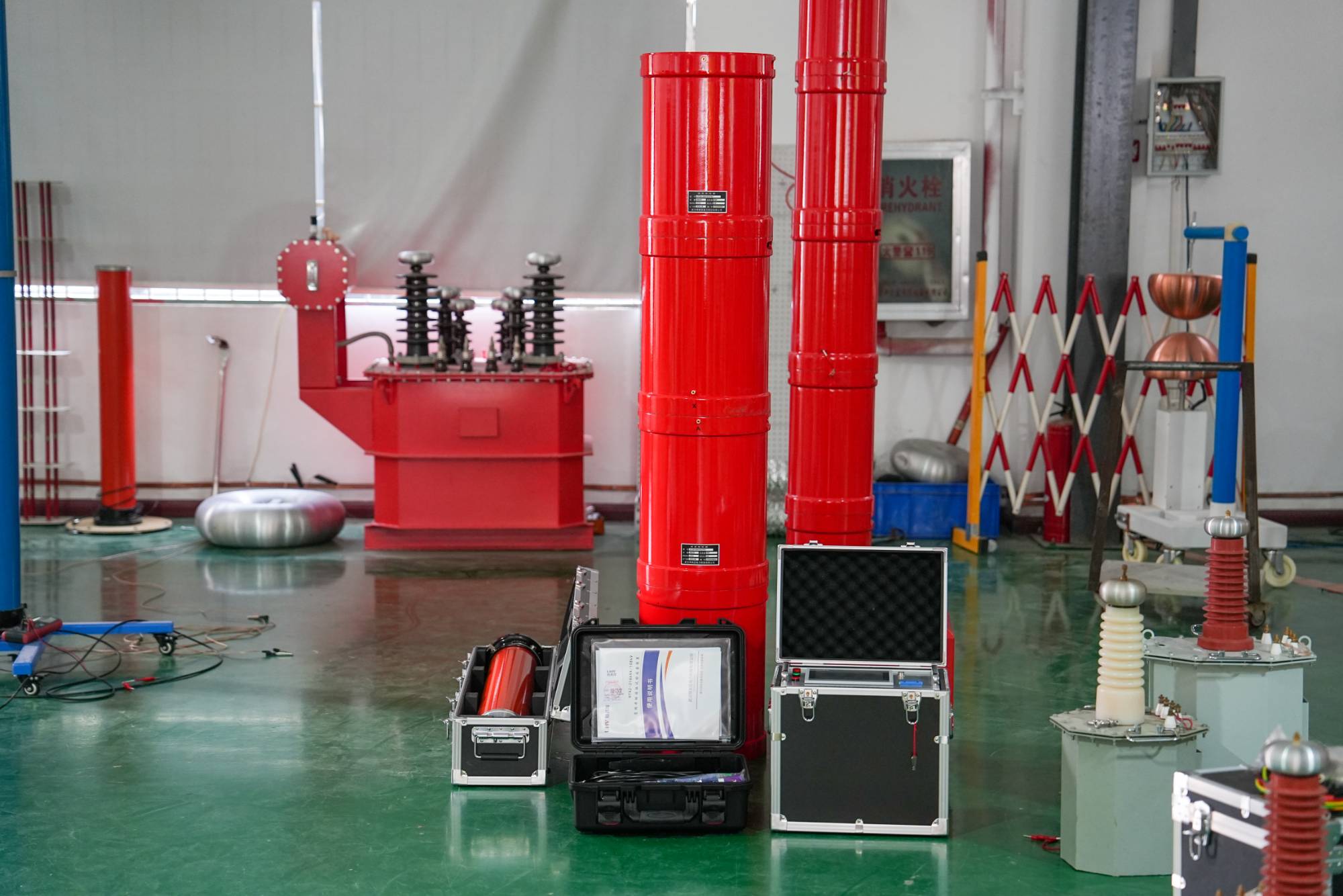
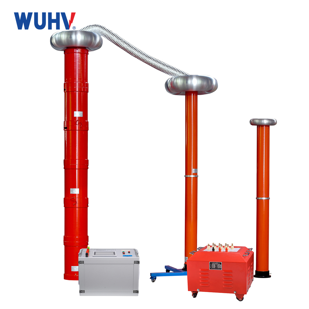
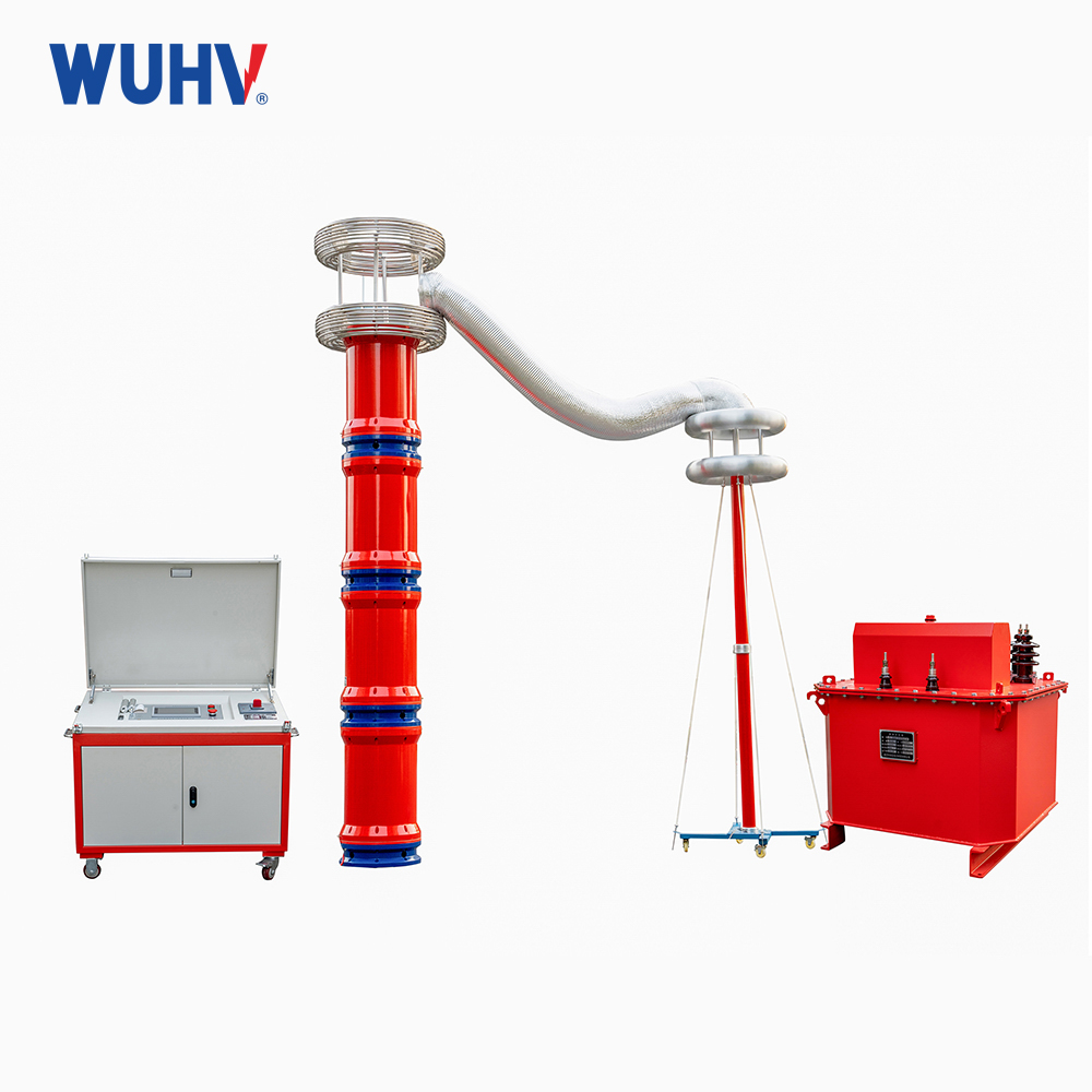
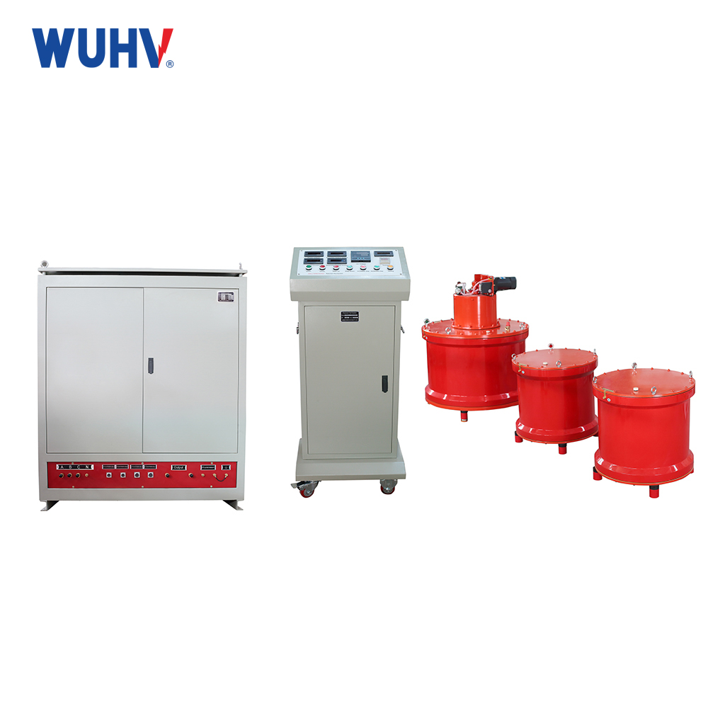
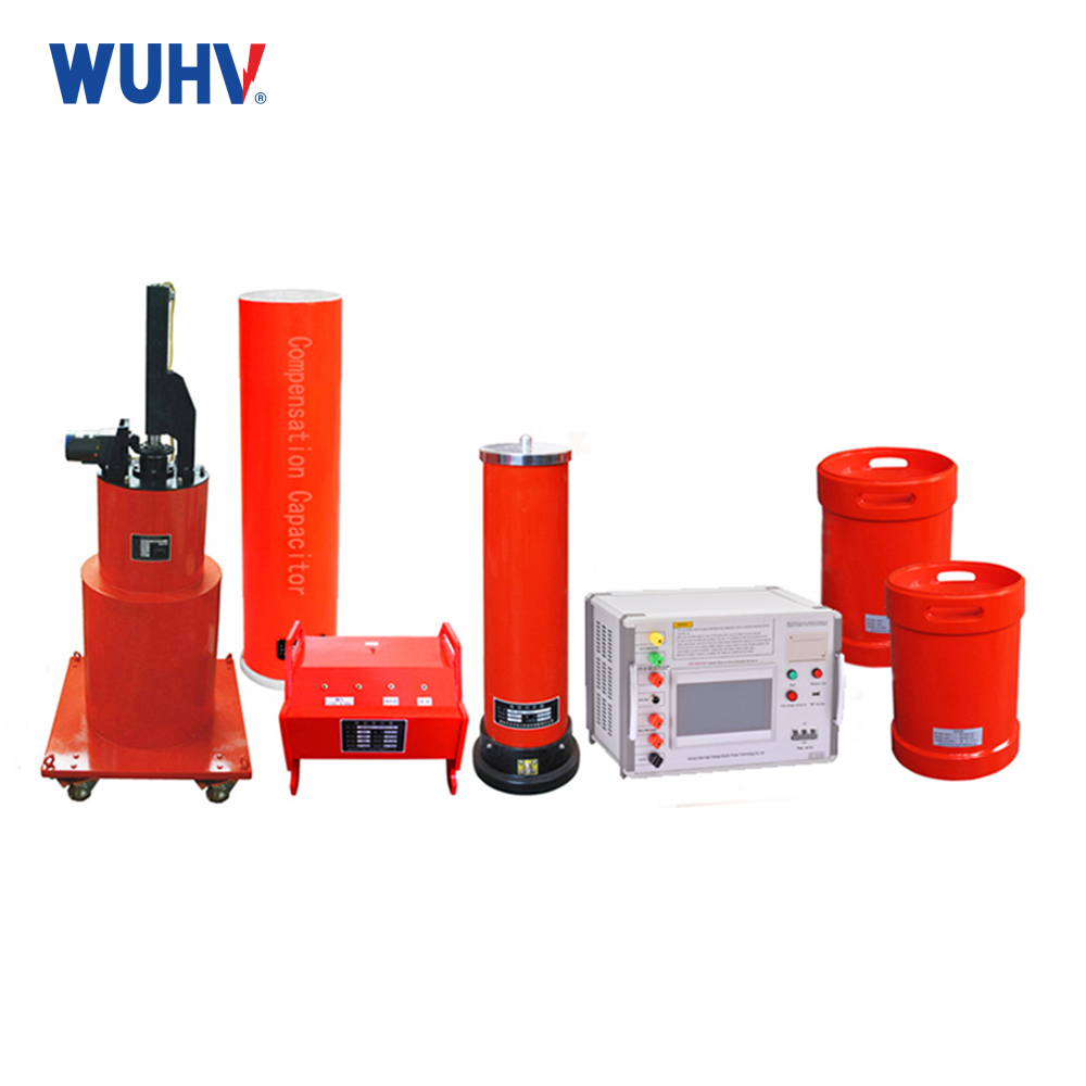
The variable frequency series resonance test device, also known as series resonance, is composed of a variable frequency power supply, excitation transformer, reactor, and capacitive voltage divider. The capacitor and reactor of the test sample form a series resonant connection; The voltage divider is connected in parallel to the test sample to measure the resonant voltage on the test sample and provide an overvoltage protection signal; The frequency modulation power output is coupled to the series resonant circuit through an excitation transformer, providing excitation power for series resonance.
harm
When resonance occurs, due to the equal inductance and capacitance, the effective values of the voltage across the inductance and capacitance are equal, that is: UL=UC。 Due to their opposite phases, these two voltages cancel each other out. The effective voltage value of a capacitor or inductor is: UL=UC=XLI0=ω0LIO=ω0LU/R。 In the formula, ω 0L/R is referred to as the quality factor of the resonant circuit, which represents the voltage ratio. Namely UC/U or UL/U.
Quality factor is an important parameter for measuring the characteristics of resonant circuits. The larger the reactance and the smaller the resistance in a circuit, the higher the quality factor. Therefore, the voltage value on the capacitor or inductor will be much higher than the applied voltage. The quality factor of general inductor and capacitor resonant circuits can reach tens or even hundreds. So series resonance is also called voltage resonance. In the power system, series resonance will generate overvoltage several times higher than the rated voltage of the grid, which poses a great threat to the safety of power equipment.


