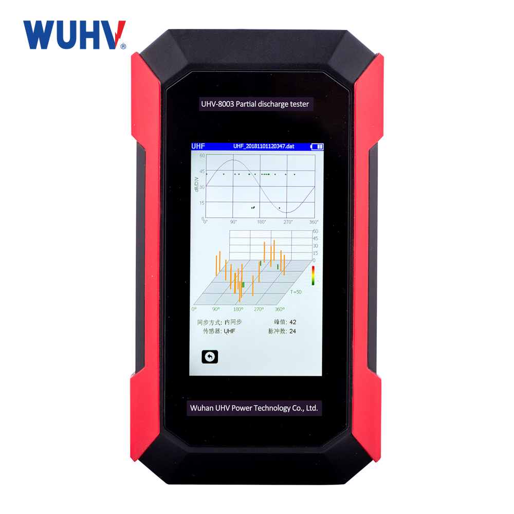
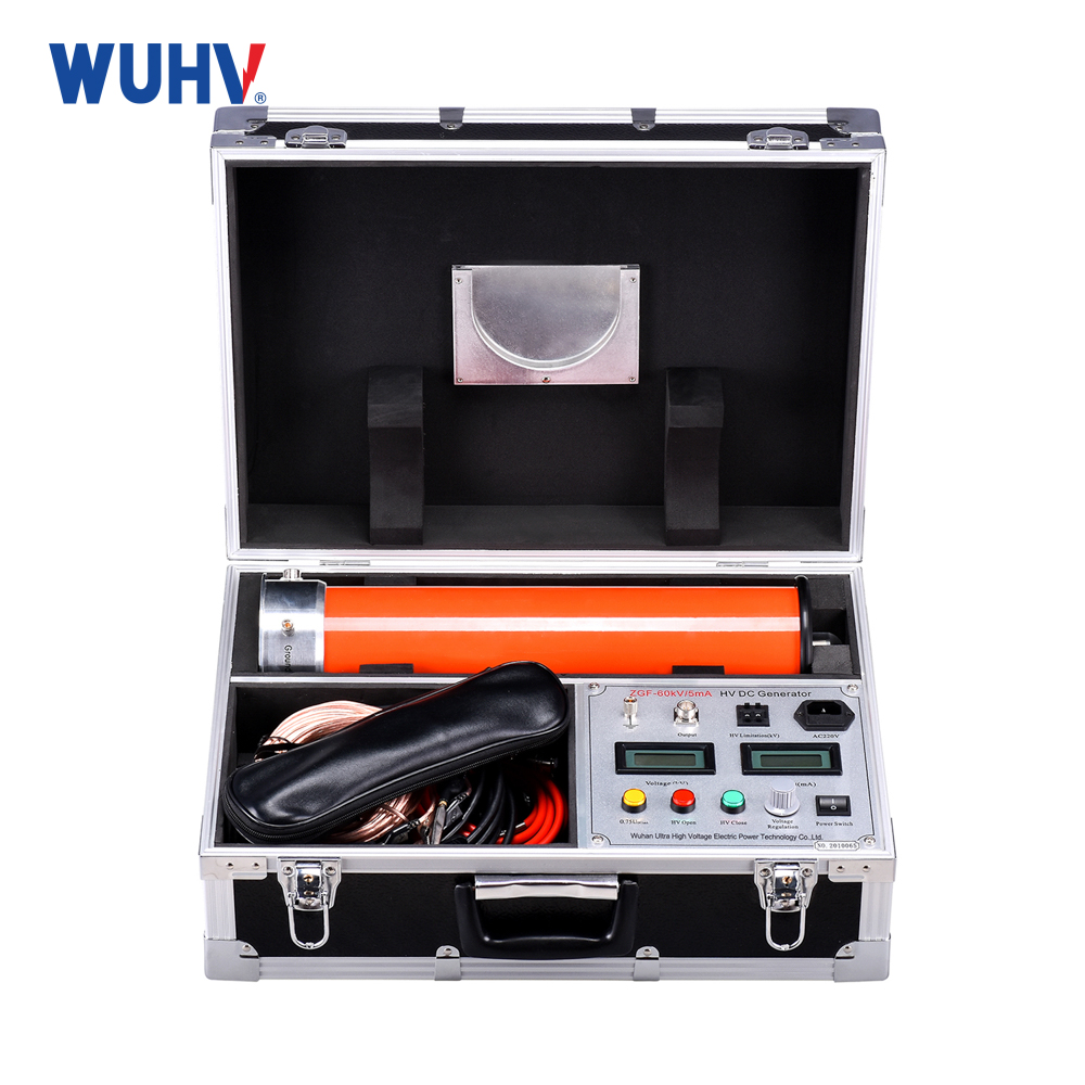
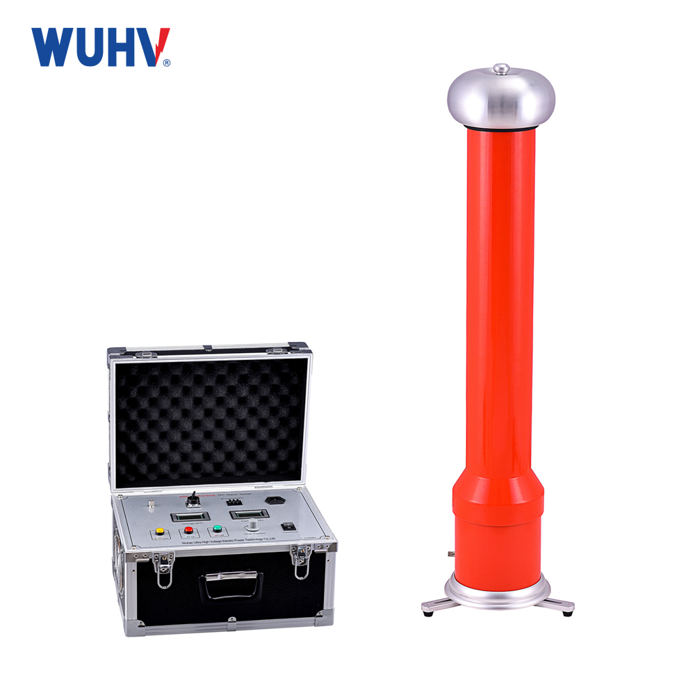
The cable fault tester under UHV power can help many power workers conduct various power tests more conveniently.
The cable fault tester consists of a transmitter, a receiver, a magnetic induction detection rod, a positioning detection frame, and other equipment. This instrument is a specialized instrument for optical cable and optical cable fault location testing. Suitable for various optical cables and cables with metal conductors (wire pairs, sheaths, shielding layers). The main functions of the street lamp cable fault tester are to locate and test the poor insulation points on the ground, detect the cable path, and test the cable burial depth.
1、 Tracer principle (signal method)
When an alternating current flows through a conductor, an alternating magnetic field is generated around the conductor, and the magnetic field lines of the field are coaxial with the conductor. At this point, if an electromagnetic coil is placed in a magnetic field, induced voltage will be generated at both ends of the coil. When moving the induction coil, the induced voltage Z generated at both ends of the coil is greater when the direction of the coil is the same as the direction of the magnetic field lines. In other words, when the coil direction is vertical, the induced voltage Z is larger; When the direction of the coil is parallel to the direction of the conductor, the induced voltage Z is smaller (as shown in Figure 2). Therefore, we obtained the 'Z big signal method' to explore the trajectory of buried cables,
2、 Positioning principle
(1) Differential potential method
If a grounding fault occurs in a buried cable, we can use the potential difference method to identify the fault point. The method is to apply a test voltage between the test point of the faulty cable and the ground, and then form a distributed electric field around the cable entry point with the entry point as the concentric point. In this electric field, there is no potential difference between any points with the same radius, but there is a potential difference between any two points with different radii (such as points a and B in the figure). Moreover, when the distance between two points is fixed, the closer the two points are to the center, the stronger the potential difference.
By utilizing this feature, we can gradually move a and B closer to the center point. When the fault point is exactly in the middle of a and B, the potential difference becomes zero. If the movement continues beyond the fault point, the polarity of the potential difference will reverse, allowing for accurate determination of the grounding point by moving back and forth.
(2) Vibration detection method
When a high resistance fault occurs in the cable, the impulse flashover method must be used to detect the fault. The grounding discharge at the fault point will cause slight vibrations on the ground. At this point, vibration sensors can be used to detect the epicenter and identify the fault point.


