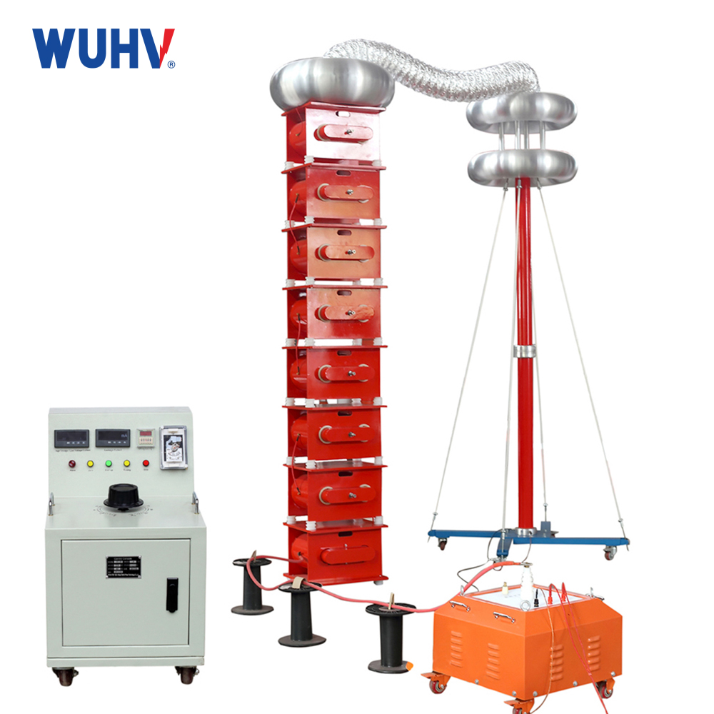
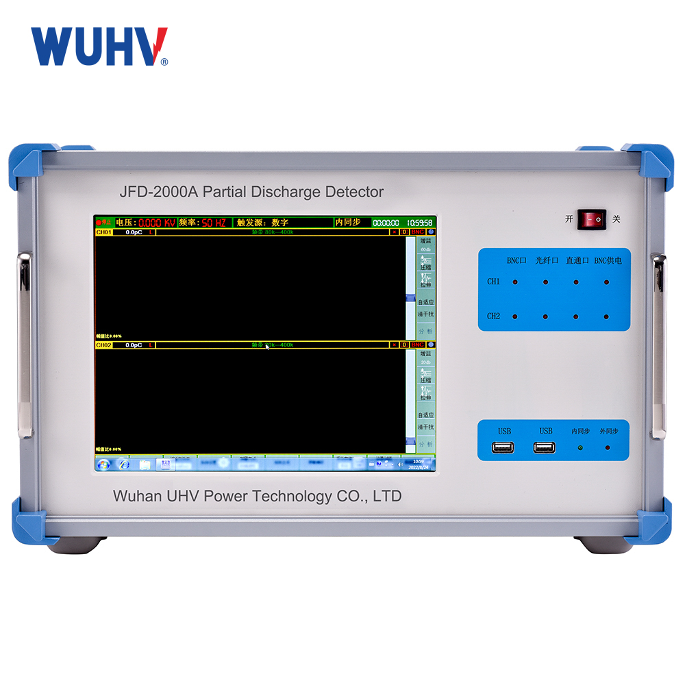
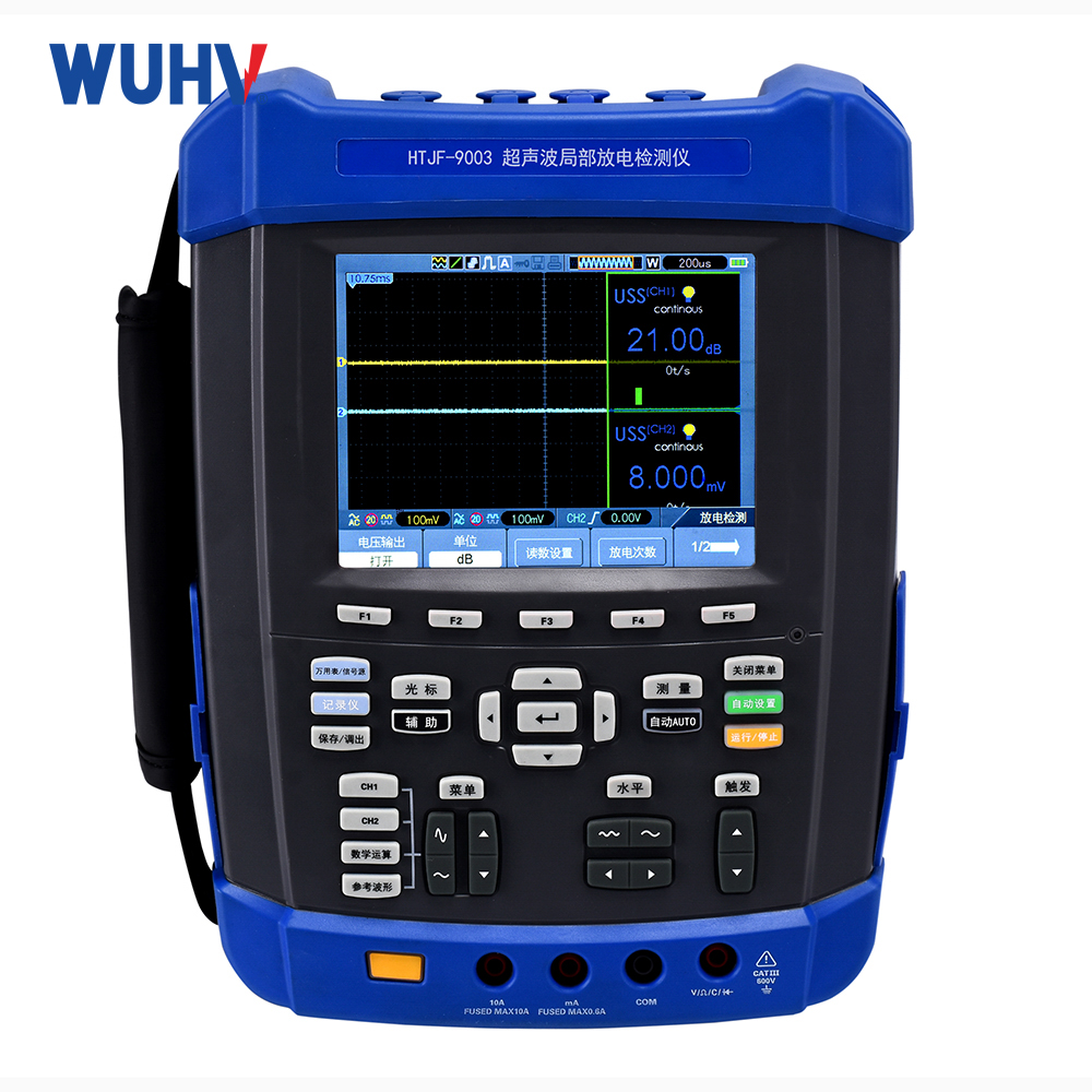
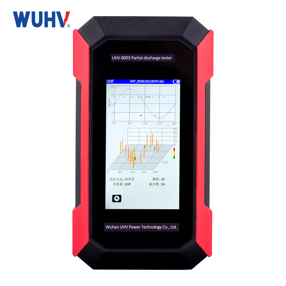
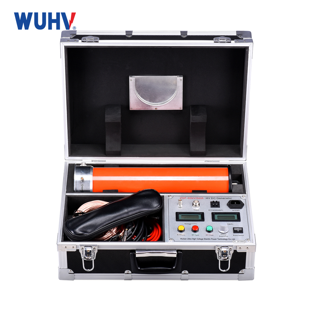
The circuit breaker tester under UHV power can help many power workers conduct various power tests more conveniently.
1. The high-voltage switch tester calibration device can only be used to verify switch testers used for metal contact testing, and does not include switch testers with closed resistance fracture and graphite contact fracture. Generally speaking, the breaking voltage of metal contacts is less than or equal to DC24V, and the breaking voltage of closing resistors is greater than DC24V. The principle of graphite contact is constant current source output, which cannot be detected by conventional methods. If the instrument has a closed door resistor function inside, the metal contact channel of the instrument can be tested. Please consult the manufacturer of the calibration device for details.
2. Method for detecting the voltage of switch circuit breakers. When the circuit breaker of the switchgear is in the open state, use the DC gear of the multimeter to detect the voltage output to the common terminal of the circuit breaker, which cannot be higher than 24V. (It is also best to use a multimeter to check the AC gear to prevent the AC voltage from damaging the testing device after the switch meter is broken). After detecting that there is no problem with the open circuit voltage of the switch, short-circuit the open circuit line to the common terminal of the open circuit and see if the status changes. If the disconnection state of the switch has not changed, it indicates that the disconnection of the switch has been damaged. If you want to test a switch device with a damaged fracture, do not wire the fracture to avoid damaging the verification device.
3. The triggering of switch testers and calibrators can only be triggered by internal and external or external to internal power sources. That is to say, when the switch instrument is an internal trigger output voltage source, the verification device must be an external trigger (the internal software setting of the device must be set to active external trigger); When the switch instrument is externally triggered to accept the input voltage source, the verification device must be internally triggered (the internal software setting of the device must be set to active internal triggering); Otherwise, it will not work properly, and if it is internal, it will damage the instrument.
4. Regarding the startup sequence of verification and calibration:
Internal triggering of switch instruments and external triggering of calibration devices. Firstly, set the triggering methods for both separately. Then adjust the calibrator to the parameter calibration interface, select to turn off or turn on calibration, and then select to start calibration, so that the calibrator is in a waiting signal input state. Then adjust the internal DC voltage of the switch tester to above 100V, and select the switch tester for closing or opening test (this closing or opening test can only be passively selected, determined by the previous verification equipment. If the previous verification equipment selected closing calibration, the switch tester must choose to turn off the switch test at this time. If the previous verification equipment selected turning on calibration, the switch tester must choose to turn on the test at this time). If the wrong testing logic is selected for the switch instrument, it will result in the inability to measure data.
The switch instrument is externally triggered, and the calibrator is internally triggered. Firstly, set the triggering methods for both separately. Then adjust the switch tester, select closing test or opening test to make the switch device wait for signal input, then adjust the calibration device to the parameter calibration interface, select closing or opening calibration (this closing or opening) test is only a passive choice, which means that the equipment determined by the previous switch tester must select to open calibration), and then select to start calibration.


