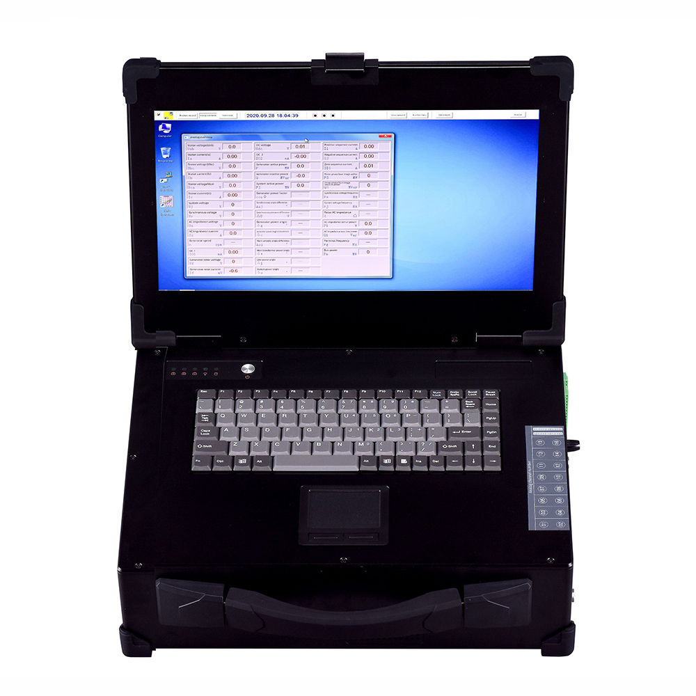
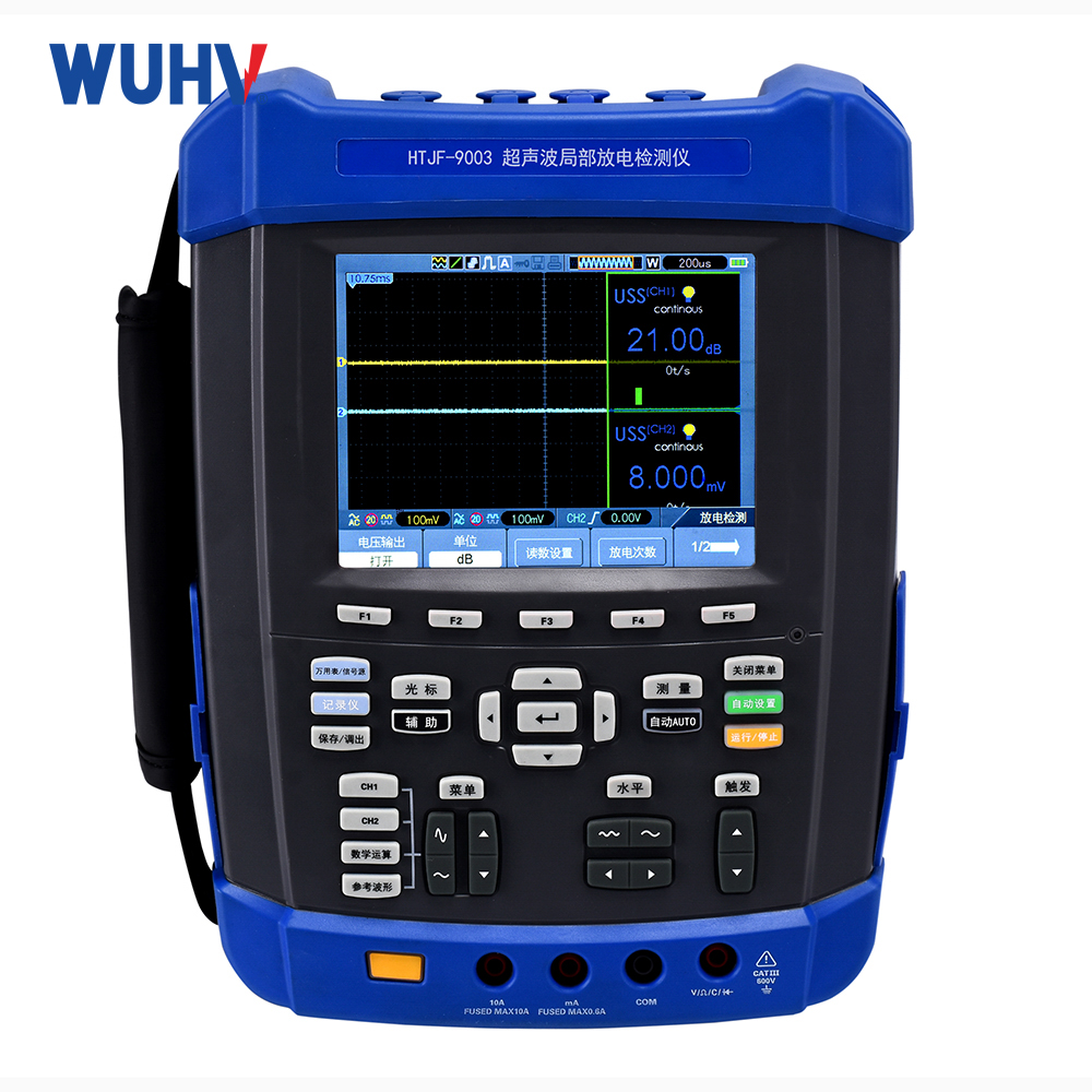
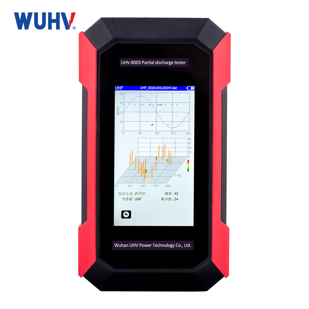
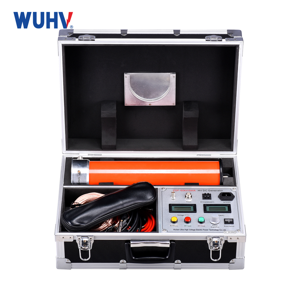
The waveform recorder under UHV power can help many power workers conduct various power tests more conveniently.
overview
The procedure for load rejection test is as follows:
Click the load suppression test button on the main interface ->Set test parameters ->Set oscilloscope environment ->Channel calibration ->Start test ->End test ->Test data analysis and processing
application
The load rejection test template is used for data recording and automatic calculation of test result parameters during the load rejection test process of steam turbine generators or hydro generator systems
TEST CONNECTION
1> Connect the voltage PT secondary side of camera terminal A to the CH1 channel of the instrument
2> Connect the unit frequency transmission signal to the CH2 channel of the instrument
3> Connect the opening signal of the passive circuit breaker to the switch channel SW1 of the instrument
Test parameter settings
The sampling frequency of the generator load suppression tester is 25kHz, the oscilloscope displays a frequency of 25Hz, the AC signal displays the effective value, and the DC signal displays the average value within 40ms. When conducting a generator load rejection test, the parameters that need to be input include the rated voltage at the no-load end, the fluctuation amplitude of the sampling voltage at the rated no-load condition, and the signal during the sampling period of the rated frequency fluctuation amplitude. CH1 channel is the secondary side of the voltage PT at the A camera terminal. The instrument displays the AC effective value and CH2 DC value. These three parameters are used for automatic calculation of test results and do not affect the testing process.
Oscilloscope Template Settings
In the load suppression test template, the environment of the oscilloscope is set based on the range of the excitation voltage, the range of the generator frequency transmitter, and their measurement units.
Example setting:
For 10kV/100V PT, the frequency transmitter 20Hz~100Hz corresponds to 4-20mA, with the terminal voltage unit in V and the frequency transmitter unit in Hz. The oscilloscope settings are as follows:
1> The name of the voltage at channel 1, with coordinates ranging from 0 to 12000V, measured in volts
2> Channel 2 Name Machine Frequency, Range 20~100, Unit Hz
Display analog channels 1 and 2, as well as switch channel 1, while the remaining analog channels and switch channels are not displayed. After setting up, click Apply to Template to save the settings
Channel calibration
According to the signal type of the connection, set the signal type and transformation ratio of channels 1 and 2.
Application examples
Example 1: For a 10kV/100V PT, the frequency transmitter 20Hz~100Hz corresponds to 4-20mA, with the terminal voltage unit in V and the frequency transmitter unit in Hz. The channel calibration settings are as follows:
1> Channel 1, select 200V range, set rate fixed-point 1 to 0V ->0V, 100V ->10000V
2> Channel 2, select 20mA range, set the rate fixed-point from 1 to 4mA ->20Hz, 20mA ->100Hz
Test program
After the test connection is completed, start the generator and connect it to the grid. Start the instrument to record the load rejection test data. After the inspection and preparation are ready, trip and close the circuit breaker to disconnect the unit and wait for it to return to no-load working state. Stop waveform recording.
Test results and parameter analysis
The parameters calculated by the instrument include maximum frequency, frequency overshoot, frequency fluctuation frequency, stabilization time, maximum voltage, voltage overshoot, voltage fluctuation frequency, and stabilization time. The overshoot, fluctuation frequency, and stabilization time are calculated according to the definition of the "Test and Acceptance Specification for Large and Medium sized Water Turbine Units".


